Insert Fieldbus Module into The PLC Configuration
To be able to use the field bus module, it must be entered into the PLC configuration of the PacDrive controller.
|
Step |
Action |
|---|---|
|
1 |
Select the PacDrive controller. |
|
2 |
Right-click > Add device. Result: The dialog box Add device appears. |
|
3 |
Select device name (for example, PROFIBUS DPV1 master). |
|
4 |
Add device button. Result: The fieldbus module is entered into the PLC configuration. |
Configuration of The Fieldbus Module
|
Step |
Action |
|---|---|
|
1 |
Select the fieldbus module in the PLC configuration. |
|
2 |
Double-click on the selected fieldbus module or right-click and select Edit object. Result: The device dialog of the field bus module with the General register is displayed. NOTE: The designation of the tab varies depending on the selected field bus module. For a PROFIBUS DPV1 slave, the designation of the tab is "PROFIBUS configuration", for example. |
In a NetXfield bus, the dialog NetX Configuration is provided as a tab in the device editor of the NetX field bus, to select the NetX chip (slot of the board) and the communication channel on this chip. The name of the setting in the dialog and the possible settings available in the selection lists are defined by the device description.

See also:
oPROFIBUS DPV1 slave: Initial parameter Connector
oEtherNet/IP Adapter: Initial parameter Connector
In order to achieve the optimum performance, the complete input / output area has to be within one memory block, i.e. individual I/O parts must not be mapped onto variables. Furthermore, all I/O variables have to be used in the program.
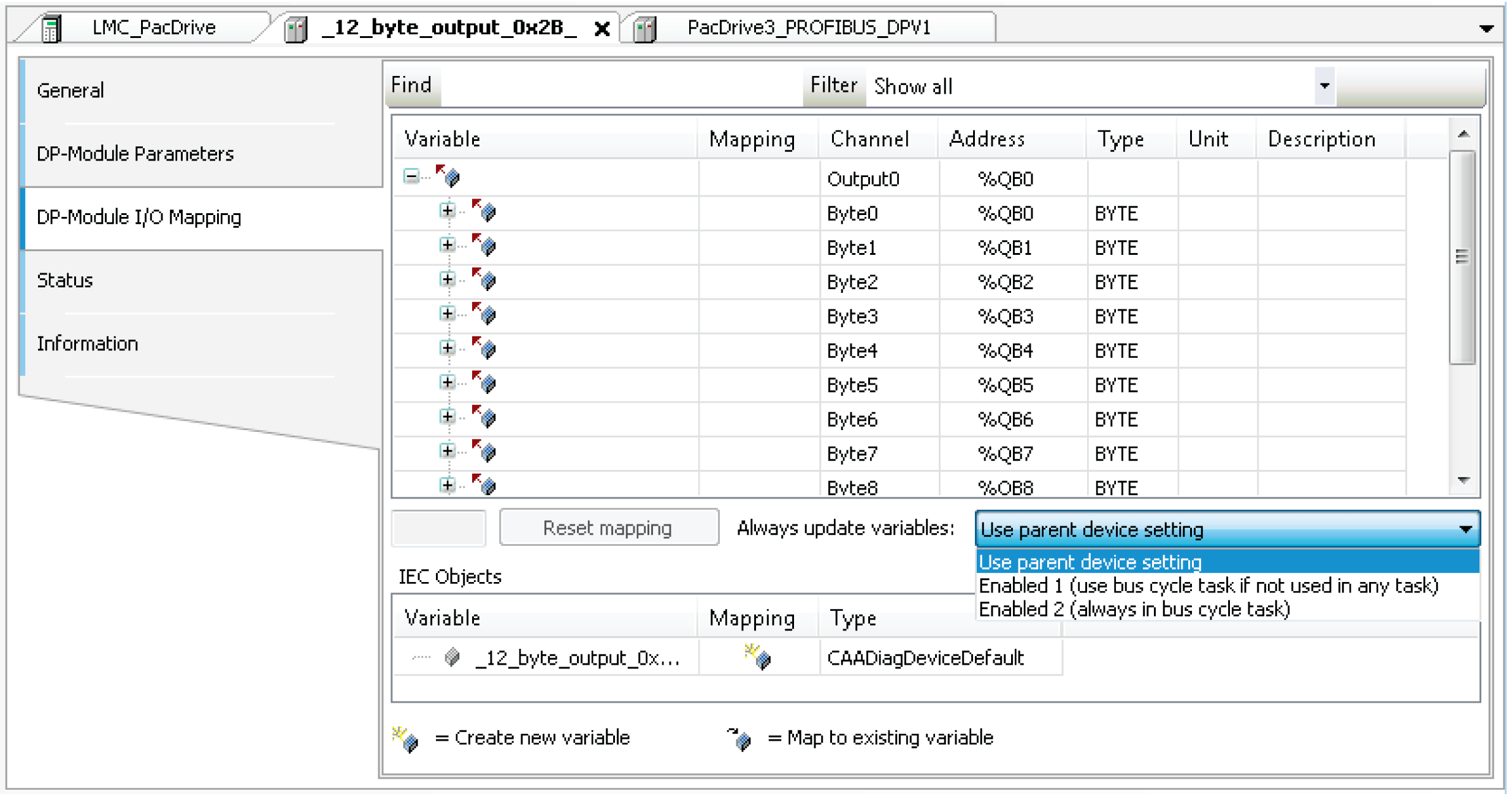
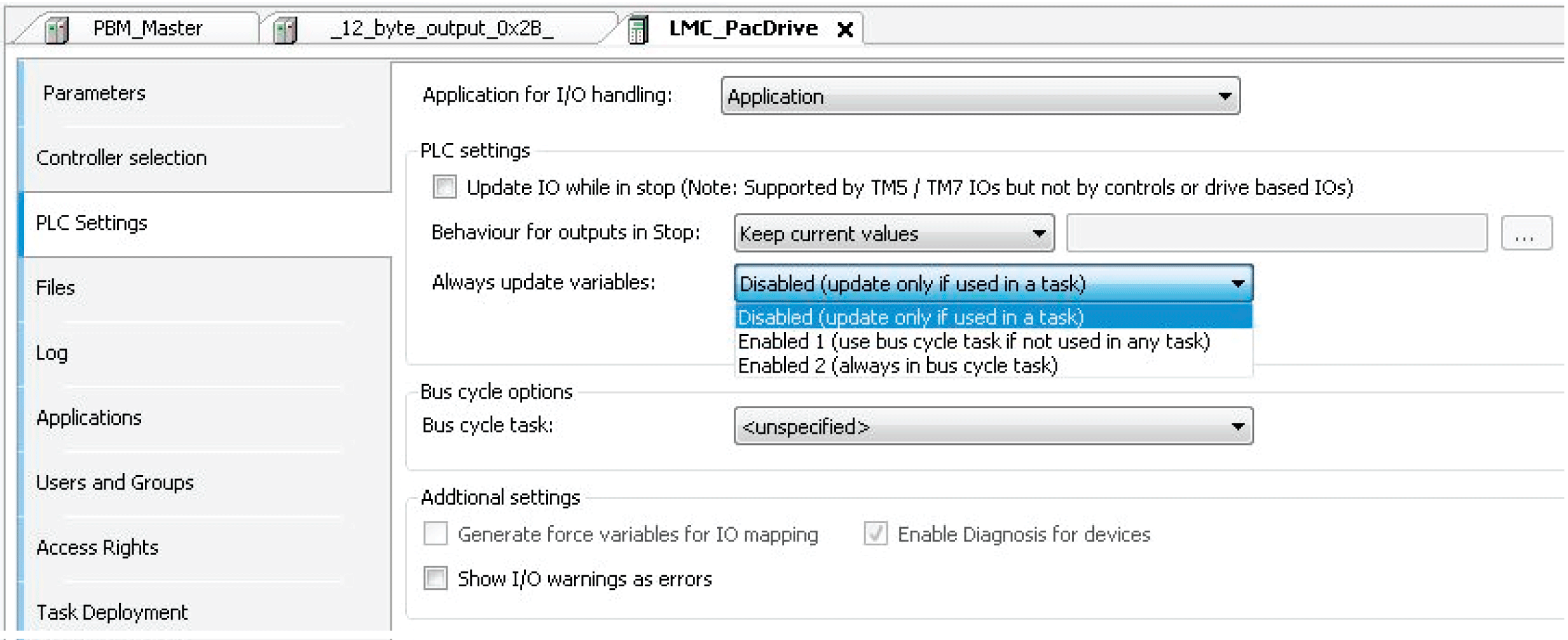
As an alternative to using all the I/O variables, it is also possible to enable the option Always update variables in the I/O Mapping dialog or the option Always update variables in the LMC_PacDrive3 > PLC Settings dialog.
Option Always update variables in the I/O Mapping dialog

Option Always update variables in the PLC Settings dialog

Global definition if the I/O variables are updated in the bus cycle task. This setting takes effect for the I/O variables of the slaves and modules only if their update setting is defined as Disabled.
oDisabled (update only if used in a task): The I/O variables are only updated if they are used in a task.
oEnabled 1 (use bus cycle task if not used in any task): The I/O variables are updated in the bus cycle task if not used in any other task.
oEnabled 2 (always in bus cycle task): All variables are updated in every cycle of the bus cycle task, regardless if they are being used or if they are mapped to an input or to an output channel. You can set this option separately for each device in the I/O Mapping dialog.
The selection list offers the tasks that are defined in the Task Configuration of the active application.
|
Step |
Action |
|---|---|
|
1 |
Select a task for your field bus and process your data in this task. |
|
2 |
For other tasks, copy your data to global variables. |
|
3 |
To verify the processing of your data, use the Task deployment tab of the device editor. Refer to the chapter "Task deployment" in the EcoStruxure Machine Expert Programming Guide. |
NOTE: For asynchronous transmission, the bus cycle options are not taken into account.
NOTE: Setting the bus cycle task to <unspecified> means that the task is selected according to controller-internal settings, which are therefore controller dependent. Setting the bus cycle task to <unspecified> may cause unintended behavior of your application.
|
|
|
UNINTENDED EQUIPMENT OPERATION |
|
Do not set the Bus cycle task to <unspecified>. |
|
Failure to follow these instructions can result in death, serious injury, or equipment damage. |
The chapter "Task deployment" in the EcoStruxure Machine Expert Programming Guide provides an overview of used I/O channels, the set bus cycle task, and the usage of channels.
NOTE: Using the same inputs and outputs in several tasks can lead to unexpected reactions in some cases.
|
|
|
UNINTENDED EQUIPMENT OPERATION |
|
If an output is written in various tasks, then the status is undefined, as this can be overwritten in each case. When the same inputs are used in various tasks, the input could change when a task is processed. This happens if the task is interrupted by a task with a higher priority and causes the process map to be read again. |
|
Failure to follow these instructions can result in death, serious injury, or equipment damage. |
Solution: At the beginning of the task, copy the input variables to variables and only work with the local variables in the rest of the code.
|
Element |
Description |
|---|---|
|
Generate force variables for IO Mapping |
This setting is only available if it is supported by the device. Consult the Programming Guide of your controller for further information. If the option is activated for each I/O channel that is assigned to a variable in the I/O Mapping dialog box, then 2 global variables will be created as soon as the application is built. These variables can be used in a HMI visualization to force the I/O value. |
|
Enable diagnostic for device |
The library CAA Device Diagnostic is added to the project automatically. For each device a function block is generated in the Applications tree. If the function block already exists, an extended FB is used (for example, EtherCAT) or an additional function block instance is added. This function block contains the general implementation for the device diagnostics. When using these function block instances, the status of all devices can be called up in the application. Furthermore, detected errors can be evaluated. The library also provides functions for the programming evaluation of the devices tree (for example, searching in child devices or jumping to the parent devices). For detailed information, see the PDF document CAA Device Diagnostic which is part of the library. |
|
Show I/O warnings as errors |
Warnings concerning the I/O configuration are displayed as detected errors. |