PackML guidelines define standardized state model to demonstrate the fundamental behavior of a packaging machine in a standardized manner.
According to the PackML guidelines each packaging machine may support many operation modes.
Each operation mode can be comprised of up to 17 states (Aborted, Aborting, Clearing, Complete, Completing, Execute, Held, Holding, Idle, Resetting, Starting, Stopped, Stopping, Suspended, Suspending, Un-Holding and Un-Suspending).
To move from one state to another, there are transitions between states. Each transition is triggered by either a state transition command or the SC (State Complete) condition.
The implementation of the PackML library focuses on the unit control mode as described in ANSI/ISA TR88.00.02-2015 standard. In all cases, when the present document refers to operation mode, it is a specific reference to unit control mode.
State models in the PackML library are based on the state model with 17 states, as defined in ANSI/ISA TR88.00.02-2015, refer to the diagram thereafter. A state model must contain these states, or a subset of these states.
A state model is defined by specifying which of these states exist for the operation mode. Transitions between states are created automatically and implicitly based on which states are selected.
ST_UnitModeDefinition is the structure representing the state model for an operation mode.
FC_InitStateModelExistingStates initializes which states exist.
FC_InitStateModelChangeStates initializes which states allow a change of operation mode.
FB_ModeManager verifies the state model for consistency and verifies whether a change of operation mode is possible and the target state in that operation mode.
FC_CheckCmd verifies whether a state transition command is valid and returns the resulting target state.
Visualization frames and FB_VisController are used to visualize the state model and provide a commissioning interface for it.
You are responsible for implementing the correct flow in the state model according to the transitions defined in the state model, as well as for implementing changes of operation mode. POUs provided in the library can help to implement this logic (FB_ModeManager and FC_CheckCmd).
You are responsible for implementing the tracking of the state and operation mode, as well as for implementing a machine behavior that corresponds to the states, the transitions, and the operation modes.
The following diagram illustrates the state model for operation modes with the 17 states present:

Within the state model, three types of states are differentiated:
|
Type of state |
Description from ANSI/ISA TR88.00.02-2015 |
Example |
|---|---|---|
|
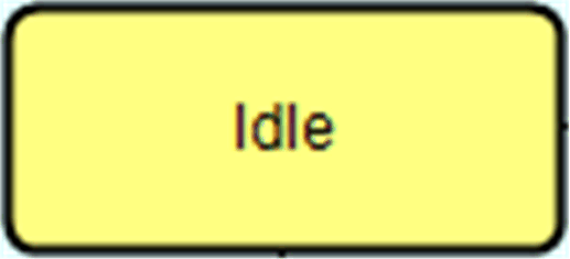
Wait state |
A state used to identify that a machine has achieved a defined set of conditions. In such a state, the machine is maintaining a status until transitioning to an acting state. |

|
|
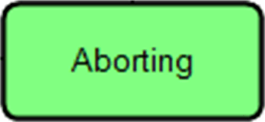
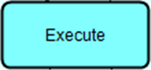
Acting state |
A state which represents some processing activity. It implies the single or repeated execution of processing steps in a logical order, for a finite time or until a specific condition has been reached. |


|
The following list describes the boundaries which define operation modes based on the state model:
oMaximum number of states: 17
The states for the operation mode can be selected from those pre-defined in the state model. Each state can appear only once and whose position is specified by the state model. You cannot add additional states, nor change the order of the states.
oState model is unidirectional.
oThe state following a Wait state must be an Acting state.
oLogic can be executed in each state.
NOTE: More rules apply to build operation modes with the PackML library. Refer to FB_ModeManager.