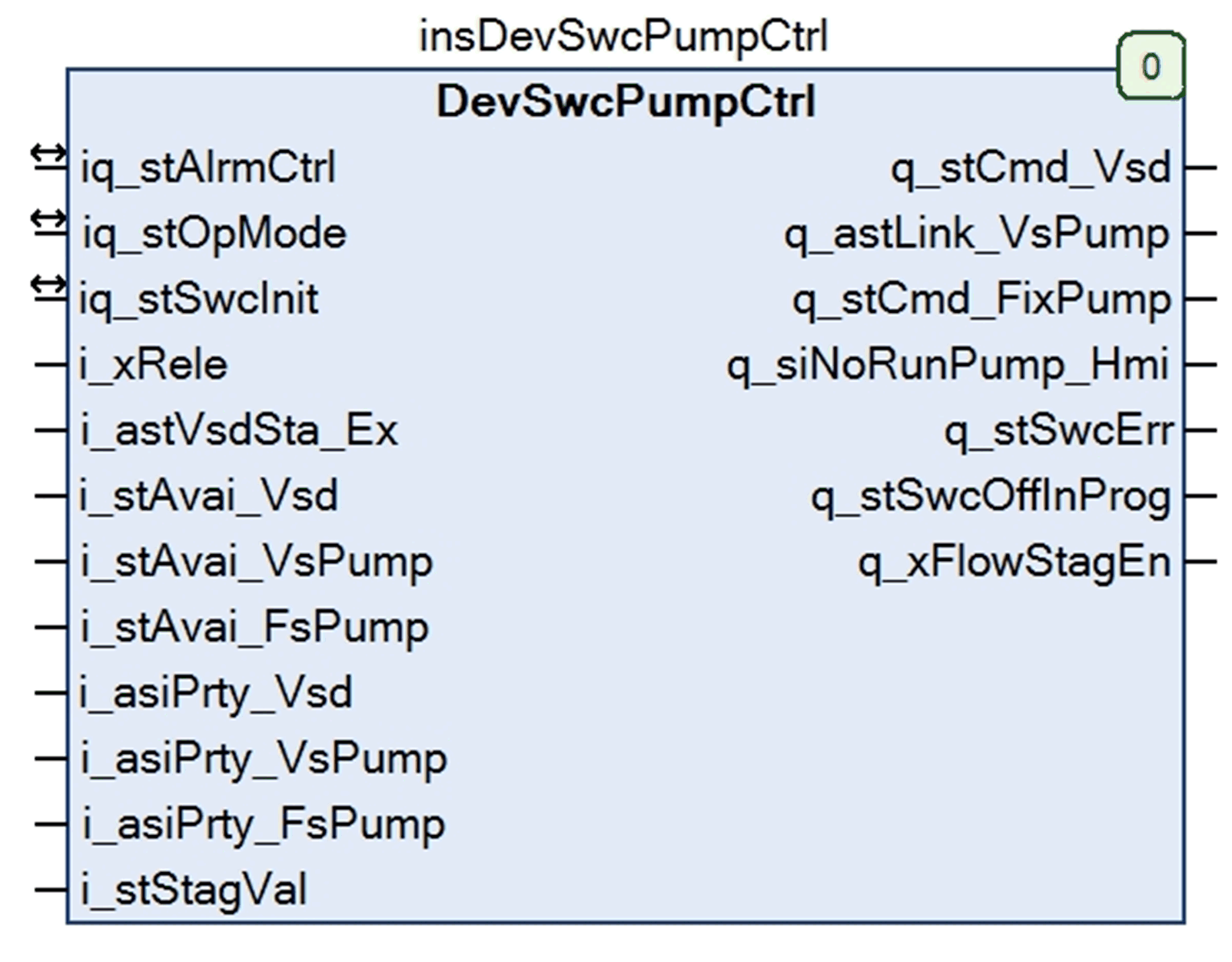
Function Block Description - DevSwcPumpCtrl

The DevSwcPumpCtrl function block has the following functions:
|
1. |
Verifying the operating mode. This function block only executes its tasks if the pumping application is running in automatic mode. In any other mode, the outputs are constantly set to their default values (0 / FALSE). |
|
2. |
Constantly verifying the availability of the used VSDs, VS pumps, and FS pumps. If one of these devices becomes unavailable, the function block switches on another device. |
|
3. |
Constantly verifying the stage value and switching VSDs, VS pumps, FS pumps if the stage value changes. oIf the stage value increases, switching a VSD, VS pump, or FS pump to run state considering the general rules and the device priority defined and generated by the OpPrty function block. If no alternative device is available, no device is switched. oIf the stage value decreases, switching a pump to stop state considering the general rules and the device priority defined and generated by the OpPrty function block. |
|
4. |
In automatic mode, stopping if an error is detected and switching to manual mode. |
|
5. |
Uses the available devices with the help of the general rules and the priority defined and generated by the OpPrty function block. |
|
6. |
Verifying whether it is possible to switch to flexible operational mode by evaluating the following questions: oIs no FS pump installed? oIs the number of VS pumps greater than the number of VSDs? oIs the bypass option enabled (xByPass = TRUE)? oIs the fixed link operational mode disabled (xFixLink = FALSE)? The flexible operational mode is the mode with the greatest availability of pumps because the VS pumps can be used independently of VSDs. |
The table describes the input/output variables of the function block:
|
Input/Output |
Data Type |
Description |
|---|---|---|
|
iq_stAlrmCtrl |
stAlrmCtrl |
Structure used for alarm handling. Refer to the structure data type description. |
|
iq_stOpMode |
stOpMode |
Determines the operating modes. If the element xAuto of the structure data type stOpMode is set to TRUE, the function block executes its tasks automatically. With another status of this element, the outputs of this function block are set to their defined fallback (default) states. Refer to the structure data type description. |
|
iq_stSwcInit |
stSwcInit |
Structure used for initialization data. Refer to the structure data type description. |
The table describes the input variables to the function block:
|
Input |
Data Type |
Description |
|---|---|---|
|
i_xRele |
BOOL |
Activates (TRUE) or stops (FALSE) the execution of the function block. |
|
i_astVsdSta_Ex |
astVsdSta |
The array of stVsdSta indicates external VSDs status. Refer to the structure data type description. |
|
i_stAvai_Vsd |
stAvai |
Structure indicating 8 available states provided by the VsdAvai function block indicating whether the VSDs are available (maximum of 4). Refer to the structure data type description. |
|
i_stAvai_VsPump |
stAvai |
Structure indicating 8 available states provided by the PumpAvai function block indicating whether the VS pumps are available (maximum of 8). Refer to the structure data type description. |
|
i_stAvai_FsPump |
stAvai |
Structure indicating 8 available states provided by the PumpAvai function block indicating whether the FS pumps are available (maximum of 8). Refer to the structure data type description. |
|
i_asiPrty_Vsd |
ARRAY [0..7] of SINT |
Priority value table for the VSDs provided by the OpPrty function block. |
|
i_asiPrty_VsPump |
ARRAY [0..7] of SINT) |
Priority value table for the VS pumps provided by the OpPrty function block. |
|
i_asiPrty_FsPump |
ARRAY [0..7] of SINT |
Priority value table for the FS pumps provided by the OpPrty function block. |
|
i_stStagVal |
stStagVal |
Structure of the stage value provided by the PumpPidStag function block. It indicates the number of pumps that is needed to generate sufficient power to maintain the user-defined pressure level. Refer to the structure data type description. |
The table describes the output variables from the function block:
|
Output |
Data Type |
Description |
|---|---|---|
|
q_stCmd_Vsd |
stCmd |
Structure used for switching the VSDs (maximum of 8) into run state. Refer to the structure data type description. |
|
q_astLink_VsPump |
ARRAY [0..7] of stLink |
Output array of stLink to link the VS pumps (maximum of 8) dynamically or constantly to one of the VSDs or directly to the power source (direct online) by using contactors. Refer to the structure data type description. |
|
q_stCmd_FsPump |
stCmd |
Structure used for switching the FS pumps (maximum of 8) into run state. Refer to the structure data type description. |
|
q_siNoRunPump_Hmi |
SINT |
Contains the number of pumps that are in run state. |
|
q_stSwcErr |
stSwcErr |
Structure used for states of detected alarms and alerts. Refer to the structure data type description for alarms and alerts. |
|
q_stSwcOffInProg |
stSwcOffInProg |
Structure to contain the switch-off-process (DCC) in progress message of up to 8 VSDs. |
|
q_xFlowStagEn |
BOOL |
When TRUE, at least 2 VSD with a corresponding VS pump is available. If no VSD / VS pump is available, this output is set to FALSE. As a result, the PumpPidStag function block stops using the flow value as a basis for stage value calculation. It uses the pressure value only. |