Mounting Jumpers of the Rack iPC Performance
You may configure the Rack iPC Performance to match the needs of your application by setting jumpers.
NOTE: A pair of needle-nose pliers may be helpful when working with jumpers.
Connectors on the Rack iPC Performance motherboard link it to external devices such as hard disk drives and a keyboard. In addition, the board has a number of jumpers that are used to configure your system for your application. The tables below list the function of each of the jumpers and connectors. Later sections in this chapter give instructions on setting jumpers.
The table describes the Rack iPC Performance jumpers and connectors:

The table describes the Rack iPC Performance jumpers and their function:
|
Label |
Function |
|---|---|
|
JCMOS1 |
CMOS clear |
|
JME1 |
Intel ME disable jumper for ME/BIOS update |
|
JWDT1 |
Watch dog reset |
|
JGREEN1 |
Deep sleep Sx mode |
|
JUSB_1,JUSB_2 |
USB port and KBMS power source switch between +5 VSB and +5 V |
|
CPUFAN_SEL1, SYSFAN_SEL1 |
FAN PWM(1-2)/DC mode selection(2-3) |
|
PSON1 |
AT(1-2) / ATX(2-3) |
You can configure your motherboard to match the needs of your application by setting the jumpers. A jumper is a metal bridge that closes an electrical circuit. It consists of two metal pins and a small metal clip (often protected by a plastic cover) that slides over the pins to connect them. To “close” (or turn on) a jumper, you connect the pins with the clip. To “open” (or turn off) a jumper, you remove the clip. Sometimes a jumper consists of a set of 3 pins, labeled 1, 2, and 3. In this case, you connect either pins 1 and 2, or 2 and 3. A pair of needle-nose pliers may be useful when setting jumpers.
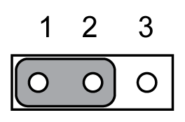
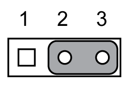
The Rack iPC motherboard contains a jumper that can erase CMOS data and reset the system BIOS information. Normally this jumper should be set with pins 1-2 closed. If you want to reset the CMOS data, set JCMOS1 to 2-3 closed for just a few seconds, and then move the jumper back to 1-2 closed. This procedure resets the CMOS to its default setting.
The table describes the CMOS data:
|
Function |
Jumper setting |
|---|---|
|
Keep CMOS data (default setting) |
|
|
Clear CMOS data |
|
The Rack iPC contains a jumper that can update for ME firmware. Generally this jumper should be set with pin 1-2 closed. If you want to update ME firmware, set JME1 to 2-3 closed for new ME firmware update.
The table describes the ME update:
|
Function |
Jumper setting |
|---|---|
|
Lock ME update (default setting) |
|
|
ME update |
|
The Rack iPC motherboard contains a jumper that provides a chassis open sensor. The buzzer on the motherboard beeps when the case is opened.
The Rack iPC contains a watchdog timer that resets the CPU. This feature means the Rack iPC Performance recovers from a software failure detection or an EMI issue. The JWDT1 jumper settings control the outcome of what the computer does in the event the watchdog timer is tripped.
The table describes the ME update:
|
Function |
Jumper setting |
|---|---|
|
Reset (default setting) |
|
|
DC |
|
The Rack iPC contains a jumper that can support energy saving for BIOS deep Sx feature. Normally this jumper should be set with pin 1-2 closed. If you want to disable, set JGREEN1 to 2-3 closed for disable.
The table describes the Deep Sx mode:
|
Function |
Jumper setting |
|---|---|
|
Enable (default setting) |
|
|
Disable |
|
The Rack iPC contains a jumper that can support USB/KBMS power source from 5 Vsb or 5 V. The default setting is 1-2 closed which is supporting USB stand-by power under S5. When the jumper is 2-3 closed, the USB/KBMS power source is switched to 5 V. If you want to disable USB stand-by power under S5, and under 2-3 closed, it does not support S3 and S4 mode.
The table describes the USB power switch:
|
Function |
Jumper setting |
|---|---|
|
+5 Vsb (default setting) |
|
|
+5 V |
|
CPU,SYSTEM Fan PWM/DC Mode Selection
The Rack iPC contains a jumper that can support PWM or DC mode, normally this jumper should be set with pin 1-2 closed. If you want to change to DC mode, set CPUFAN_SEL1, SYSFAN_SEL1 to 2-3 closed for disable.
The table describes the PWM/DC mode selection:
|
Function |
Jumper setting |
|---|---|
|
PWM mode (default setting) |
|
|
DC mode |
|
The table describes the ATX/AT mode selector:
|
Function |
Jumper setting |
|---|---|
|
AT mode |
|
|
ATX mode (default setting) |
|
|
AD PCI slot INT |
PCI1 |
PCI3 |
PCI4 |
|---|---|---|---|
|
AD16 |
AD21 |
AD22 |
|
|
A |
A |
F |
G |
|
B |
B |
G |
H |
|
C |
C |
H |
E |
|
D |
D |
E |
F |
|
Step |
Action |
|---|---|
|
1 |
Remove the power. |
|
2 |
Insert the jumper. |
The table describes the setting for the LVDS power setting:
|
CN17 |
LVDS power |
|---|---|
|
Setting |
Function |
|
1-3 2-4 |
VDD_DSUB (pin 7 and pin 20) of LVDS pin is 5 Vdc |
|
3-5 4-6 |
VDD_DSUB (pin 7 and pin 20) of LVDS pin is 3.3 Vdc |
The table describes the setting for the clear CMOS setting:
|
CN3 |
Clear CMOS |
|---|---|
|
Setting |
Function |
|
– |
Normal (default setting) |
|
1-2 |
Clear CMOS |