Configuration of the Main Type in Modulo-loop Mode
|
Step |
Action |
|---|---|
|
1 |
In the Devices tree, double-click Embedded Functions > HSC. |
|
2 |
Set the type to Main from the HSC0• > Type drop down menu. |
|
3 |
The instance of the Main type is created, you can rename it from the Variable field. |
|
4 |
Set the mode to Modulo-loop from the HSC0• > Parameters > Mode drop down menu. |
|
5 |
Set the modulo value for Parameters > Preset/Modulo |
|
6 |
Select an input mode value from the HSC0• > Clock Inputs > Input mode drop down menu. This enables the A Filter (and B Filter, depending on the Input mode used). |
|
7 |
Set the anti-bounce filtering value from the Clock Inputs > A Filter (and B Filter, when applicable) drop down menu. |
|
8 |
Optionally, enable the SYNC, EN (only if input mode = Single Phase) and CAP auxiliary inputs from the HSC0• > Auxiliary Inputs > SYNC or EN or CAP drop down menus, to enable the Synchronization function, Enable function and Capture function on a physical input. |
|
9 |
Optionally, enable the thresholds from the drop down menu, by selecting HSC0• > Thresholds > Threshold 0 > Enable/Disabled to authorize the Compare function and to configure the Reflex Outputs. NOTE: For the Modulo-Loop mode, configured values must follow the rule: 0 < Threshold 0 Value < Threshold 1 Value < (Modulo - 1) |
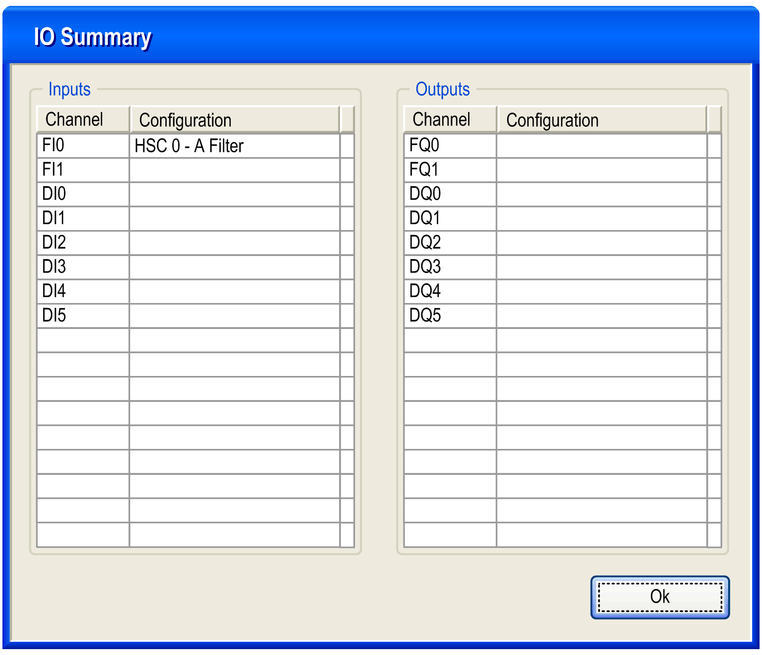
Click the IO Summarize... button to display the input and output assignments.

Refer to the hardware guide for wiring details.
The filtering value on the Main type input determines the counter maximum frequency as shown in the table:
|
Input |
Filter value |
Maximum counter frequency |
|---|---|---|
|
A, B |
4 µs |
50 kHz |
|
40 µs |
14.5 kHz |