This function block returns the PTO detected error code.
To see the general representation in IL or ST language, refer to the chapter Function and Function Block Representation.
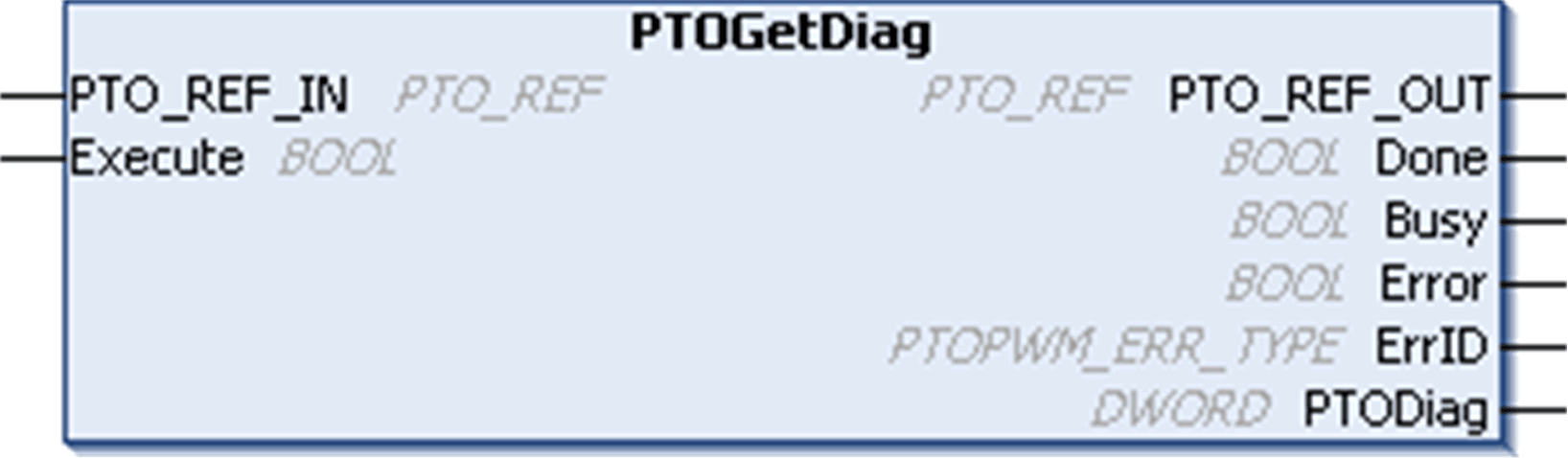
This table describes the input variables:
|
Inputs |
Type |
Comment |
|---|---|---|
|
PTO_REF_IN |
Reference to the PTO channel. To be connected to the PTO_REF of the PTOSimple or the PTO_REF_OUT of the PTO function blocks. |
|
|
Execute |
BOOL |
On rising edge, starts the function block execution. When FALSE, resets the outputs of the function block when its execution terminates. |
This table describes the output variables:
|
Outputs |
Type |
Comment |
|
|---|---|---|---|
|
PTO_REF_OUT |
Reference to the PTO channel. To be connected with the PTO_REF_IN input pin of the PTO function blocks. |
||
|
Done |
BOOL |
TRUE = indicates that PTODiag is valid. Function block execution is finished. |
|
|
Busy |
BOOL |
TRUE = indicates that the function block execution is in progress. |
|
|
Error |
BOOL |
TRUE = indicates that an error was detected. Function block execution is finished. |
|
|
ErrID |
When Error is TRUE: type of the detected error. |
||
|
PTODiag |
DWORD |
When Done is TRUE: Diagnostic error code (see table below). |
|
|
DWORD bit |
Meaning |
|---|---|
|
0...3 |
Not used |
|
4 |
Internal error detected |
|
5...6 |
Not used |
|
7 |
Configuration error detected |
|
8...16 |
Not used |
|
17 |
Drive not ready (auxiliary input DriveReady is FALSE) |
|
18...20 |
Not used |
|
21 |
Reserved |
|
22 |
Invalid Frequency |
|
23 |
Invalid Acceleration |
|
24 |
Invalid Deceleration |
|
25 |
Command rejected (PTO_AXIS_ERROR, or new PTO command is triggered before the last operation is completed) |
|
26 |
Invalid Direction |
|
27...31 |
Not used |
NOTE: For more information about Done, Busy, CommandAborted and Execution pins, refer to General Information on Function Block Management.