Details of the application example
This section describes a possible application where the SF_MutingPar_2Sensor function block can be used to implement parallel muting with two sensors.
The function block must only be used in an actual application once a risk analysis has been conducted.
Details of the risk category/SIL/PL have not been included here, as classification is always based on the application in which the function block is used.
NOTE:
The use of the function block alone is not sufficient to execute the safety-related function according to the Cat./SIL/PL determined by the risk analysis. In conjunction with the safety-related I/O device used, additional measures must be taken to meet the requirements of the safety-related function. These include, for example, the appropriate wiring and parameterization of the inputs and outputs as well as measures to exclude (design out) errors that cannot be detected. For additional information, refer to the documentation provided with the safety-related I/O device used.
NOTE:
Refer to the notes in the User Manual on proper electrical connection of the Safety Logic Controller and the extension modules (e.g., connecting the muting sensors and the safety-related equipment).
Parallel muting with two sensors, with start-up inhibit
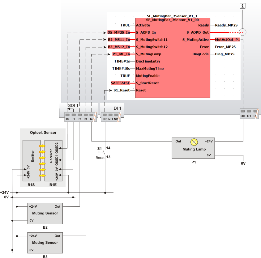
The example describes the connection of two muting sensors arranged in parallel to the safety-related SF_MutingPar_2Sensor function block.
The sensors/actuators are connected to the input/output devices and the function block as follows:
Receiver B1E of the safety-related equipment (two-channel light grid) is connected to input terminals I0 and I1 of the safety-related input device SDI 1.
Two-channel evaluation of the signal from the light grid for equivalence occurs in the safety-related input device, which has been parameterized accordingly. The resulting signal is assigned to the global I/O variable OS_MP2S_In, which in turn is connected to the S_AOPD_In input of the function block. It is SAFETRUE if both inputs of the safety-related input device SDI 1 are SAFETRUE at the same time (light grid not interrupted) and the input device does not report any errors as regards exceeding the discrepancy time. For more detailed information, refer to the descriptions of the input parameters of the safety-related input device.
NOTE:
Cross-circuit monitoring is not performed by the function block. It is your responsibility to perform this monitoring function outside of this function block in the safety-related control system.
The single-channel muting sensors arranged in parallel are connected to input terminals I2 and I3 of the safety-related input device SDI 1. The terminal I2 is assigned to the global I/O variable B2_MS11_In, which in turn is connected to the function block input S_MutingSwitch11. The terminal I3 is assigned to the global I/O variable B3_MS12_In, which in turn is connected to the function block input S_MutingSwitch12.
S_StartReset = SAFEFALSE specifies a start-up inhibit after the Safety Logic Controller has been started up or the function block has been activated. The start-up inhibit is only removed if there is a positive signal edge at the Reset input. To this end, the S1 reset button is connected to input NI0 of the standard input device DI 1. The assigned global I/O variable S1_Reset is connected to the Reset input.
The S_MutingActive output of the function block controls muting lamp P1 in order to signal the state "muting active". This muting lamp is connected to output terminal O0 of the Safety Logic Controller. The assigned global I/O variable MutActOut_P1 is connected to the S_MutingActive function block input.
The feedback signal of muting lamp P1 is connected to input I4 of the safety-related input device SDI 1. The assigned global I/O variable P1_ML_In in turn is connected to the S_MutingLamp function block input.
The function block is perpetually activated by the TRUE constant at the Activate input. A TRUE constant is also applied to the MutingEnable input (permanent enable signal for the muting operation by means of MutingEnable = TRUE).
NOTE:
The S_AOPD_Out enable output of the SF_MutingPar_2Sensor function block is connected to an output terminal of the application via a global I/O variable or via other safety-related functions/function blocks.
Connect the S_AOPD_Out enable output of the SF_MutingPar_2Sensor function block to the S_OutControl input of the SF_EDM function block, for example, thus implementing a two-channel output connection.
|
B1 |
Two-channel light grid (B1S = optoelectronic transmitter, B1E = optoelectronic receiver) |
|
B2, B3 |
Optoelectronic muting sensors, single-channel, located in front of the light grid |
|
P1 |
Muting lamp with single-channel feedback signal, monitored by safety logic |
|
|
See note above the illustration. |
