The safety-related SF_MutingSeq function block executes the function "sequential muting with four sensors" within an application.
To this end, it evaluates the following signals:
the signals of four muting sensors,
the status signal of the safety-related equipment (light grid),
the feedback signal from the muting lamp,
an enable signal for the muting operation.
A start-up inhibit can be specified at S_StartReset.
The function block switches the enable signal at the S_AOPD_Out output in accordance with the input signals present. It executes stop category 0 at this output.
NOTE:
The signal at the S_AOPD_Out output is the enable signal for the entire process. In order to process the enable or, equally, the request for the defined safe state in the functional safety system, the signal must be used in the safety logic in such a way that a SAFEFALSE signal at the S_AOPD_Out output stops the zone of operation from being used.
NOTE:
Depending on the result of the risk analysis, optical, mechanical or inductive sensors such as reflection light sensors, mechanical or inductive switches can be used as muting sensors. Optical sensors serve as examples in the help information.
The overall muting operation is divided into different muting sequences.
NOTE:
Only the material flow direction from muting sensors MutingSwitch11 MutingSwitch12 to muting sensors MutingSwitch21MutingSwitch22 is described in the following. This is illustrated in the graphic in the function block overview.
The function block also supports the opposite material flow direction from muting sensors MutingSwitch22MutingSwitch21 to muting sensors MutingSwitch12MutingSwitch11. The functional sequence remains identical.
Protecting the zone of operation.
The safety-related equipment is active when muting is not active: If the function block does not detect an active muting operation at the muting inputs, a SAFEFALSE signal from the light grid ("object detected") leads to the defined safe state SAFEFALSE at the S_AOPD_Out output (e.g., "stop machine").
Activating the muting operation.
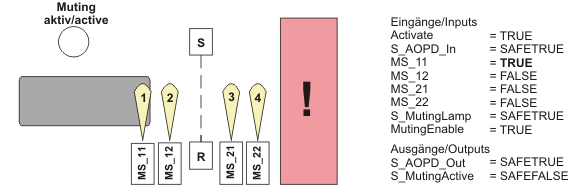
The safety-related equipment is deactivated: When the muting sensors located before the safety-related equipment switch from FALSE to TRUE one after the other (i.e., first MutingSwitch11 and then MutingSwitch12) (because both have detected an object), the muting operation is activated and the safety-related equipment deactivated.
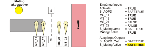
Muting operation is active.
The safety-related equipment is deactivated for as long as the muting operation is active and the sensors detect an object permissible for the muting operation.
A SAFEFALSE signal from the light grid ("object detected") does in this case not cause the S_AOPD_Out output to switch to the defined safe state SAFEFALSE (e.g., "stop machine").
The muting operation remains active as long as the requirements for a valid muting sequence are met and when the muting operation is completed properly within the maximum muting time set at MaxMutingTime. If it is not, the S_AOPD_Out output switches to the defined safe state SAFEFALSE (e.g., "stop machine").
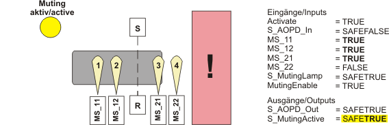
Completing the muting operation.
The safety-related equipment is active again. The muting operation is complete when the first muting sensor located behind the safety-related equipment (at the MutingSwitch21 input) switches back from TRUE to FALSE, i.e., an object is no longer detected in the detection area. The safety-related equipment is reactivated at the same time when the S_MutingActive output switches to SAFEFALSE.
Further Information
Refer also to the "Invalid muting sequences" section in this context.
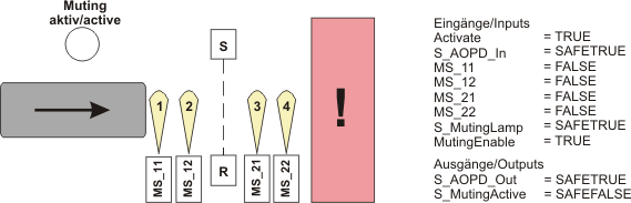
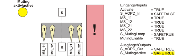
The graphic below shows an example of a muting operation.
NOTE:
In the graphic, only the values of the inputs and outputs which are relevant for this illustration are given.
Explanatory notes:
MS_11: Muting sensor 1, connected to function block input MutingSwitch11 and
MS_12: Muting sensor 2, connected to function block input MutingSwitch12.
These two sensors are positioned before the safety-related equipment in the material flow direction of the assembly conveyor.
The detection areas of the muting sensors are shown as "yellow light beams".
MS_21: Muting sensor 3, connected to function block input MutingSwitch21 and
MS_22: Muting sensor 4, connected to function block input MutingSwitch22.
These two sensors are positioned behind the safety-related equipment in the material flow direction of the assembly conveyor.
Signaling unit (e.g., lamp) "muting active", controlled via function block output S_MutingActive.
S/R: Safety-related equipment (e.g., light grid), consisting of a transmitter (S) and a receiver (R), connected to function block input S_AOPD_In. The function of this safety-related equipment is deactivated/activated by means of the muting operation.
|
|
The light beams of all the muting sensors are not interrupted. The muting operation is not (yet) active. |
|
|
|
|
|
|
|
|
|
|
|
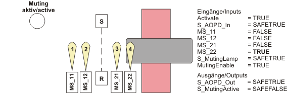
NOTE: The muting sensors 1 and 2 must not report FALSE, before both sensors 3 and 4 have reported TRUE. Otherwise the function block detects an error.
|
|
|
|
Invalid states at the muting sensors are detected as errors (Error = TRUE). In the event of an error, the S_AOPD_Out output always switches to the defined safe state (S_AOPD_Out = SAFEFALSE).
Invalid states always occur when the following valid muting operation is not adhered to:
For a material flow direction from left to right: first, MutingSwitch11 must become TRUE and subsequently MutingSwitch12. Both inputs must remain TRUE until MutingSwitch21 and then MutingSwitch22 also become TRUE.
For a material flow direction from right to left: first, MutingSwitch22 must become TRUE and subsequently MutingSwitch21. Both inputs must remain TRUE until MutingSwitch12 and then MutingSwitch11 also become TRUE.
Start-up inhibit (S_StartReset)
S_StartReset is used to specify the start-up inhibit after activating the function block and/or starting the Safety Logic Controller.
|
S_StartReset = SAFEFALSE |
After the Safety Logic Controller has been started up and/or the function block has been activated at input Activate, the start-up inhibit is active. The start-up inhibit is only removed if there is a positive signal edge at the Reset input. Refer to the first hazard message below this table. |
|
S_StartReset = SAFETRUE |
After the Safety Logic Controller has been started up and/or the function block has been activated at input Activate, no start-up inhibit is active. Refer to the second hazard message below this table. |
Removing the start-up inhibit by means of a positive signal edge at the Reset input can cause the S_AOPD_Out output to switch to SAFETRUE immediately (depending on the status of the other inputs).
WARNING
UNINTENDED START-UP
Verify the impact of removing the start-up inhibit by means of a positive signal edge at the Reset input.
Make certain that appropriate procedures and measures (according to applicable sector standards) have been taken to help avoid hazardous situations when removing the start-up inhibit.
Do not enter the zone of operation when removing the start-up inhibit.
Ensure that no other persons can access the zone of operation when removing the start-up inhibit.
Use appropriate safety interlocks where personnel and/or equipment hazards exist.
Failure to follow these instructions can result in death, serious injury, or equipment damage.
WARNING
NON-CONFORMANCE TO SAFETY FUNCTION REQUIREMENTS
Verify the impact of a deactivated start-up inhibit (S_StartReset = SAFETRUE) on your machine or process prior to implementation.
Observe the regulations given by relevant sector standards regarding the start-up inhibit.
Verify that a suitable start-up inhibit is in place at another location or using other means if the start-up inhibit is deactivated by setting S_StartReset = SAFETRUE.
Failure to follow these instructions can result in death, serious injury, or equipment damage.