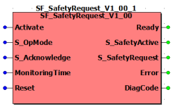
The following description is valid for the function block SF_SafetyRequest_V1_0z, Version 1.0z (where z = 0 to 9).
Short description
|
The safety-related SF_SafetyRequest function block supports the function "Request of a safety-related function" in an application (e.g., safe stop or safely limited speed). Depending on the status at input S_OpMode, the safety-related function block requests the safety-related function at the periphery. Based on the signal for requesting a safety-related function (at the S_OpMode input) and the feedback signal about its correct execution (at the S_Acknowledge input), the S_SafetyActive output signal is controlled. This output signal is typically used to send a signal confirming the requested operating mode being activated to a subsequent safety-related function block. The maximum permissible response time within which confirmation is expected must be parameterized at the MonitoringTime input and is monitored by the safety-related function block. |

|
The function block thus serves as interface between the functional safety system (consisting of the Safety Logic Controller and safety-related input/output modules) and the connected safety-related periphery, for example a safety-related drive.
NOTE:
A start-up inhibit and restart inhibit which cannot be deactivated are specified in the safety-related SF_SafetyRequest function block (see topic "Functional description"). An active start-up inhibit/restart inhibit must be removed manually by a positive signal edge at the Reset input.
Function block inputs
Click the corresponding hyperlinks to obtain detailed information on the items below.
|
Name |
Short description |
Value |
|
State-controlled input for activating the function block. Data type: BOOL Initial value: FALSE |
|
|
|
State-controlled input for requesting the execution of a safety-related function in the connected safety-related periphery. Data type: SAFEBOOL Initial value: SAFEFALSE |
|
|
|
State-controlled input which processes the status feedback of the connected safety-related periphery. Data type: SAFEBOOL Initial value: SAFEFALSE |
|
|
|
Input for specifying the maximum permissible response time between the request of the safety-related function at the S_OpMode input and confirmation of its execution at the S_Acknowledge feedback input. Data type: TIME Initial value: #0ms If the specified time value is exceeded, the Error output switches to TRUE and the S_Acknowledge enable output switches to SAFEFALSE. |
The time value to be configured depends on the safety response time of the functional safety system. The safety response time is the time between arrival of the signal at the input channel and output of the switch-off signal at the device output. In order to calculate the safety response time of your functional safety system, select the menu item 'Project > Response time calculator' in EcoStruxure Machine Expert - Safety. More information can be found in the chapter "Safe response time" of the EcoStruxure Machine Expert - Safety Online Help. Enter a time value according to your risk analysis. Refer to the first hazard message below this table. |
|
|
Edge-triggered input for the reset signal:
Data type: BOOL Initial value: FALSE NOTE: Resetting does not occur with a negative (falling) edge, as specified by standard EN ISO 13849-1, but with a positive (rising) edge. Refer to the second hazard message below this table. |
|
WARNING
NON-CONFORMANCE TO SAFETY FUNCTION REQUIREMENTS
Verify that the time value set at MonitoringTime corresponds to your risk analysis.
Be sure that your risk analysis includes an evaluation for incorrectly setting the time value for the MonitoringTime parameter.
Validate the overall safety-related function with regard to the set MonitoringTime value and thoroughly test the application.
Failure to follow these instructions can result in death, serious injury, or equipment damage.
If the safety-related function is no longer requested (S_OpMode = SAFETRUE) before or during the rising signal edge at the Reset input (for resetting errors), this can signal to the system/machine that a request for the safety-related function is no longer present. This can lead to a risk, for example with the machine/system starting up immediately.
WARNING
UNINTENDED START-UP
Include in your risk analysis the impact of the reset by means of a positive signal edge at the Reset input.
Make certain that appropriate procedures and measures (according to applicable sector standards) have been established to help avoid hazardous situations when resetting.
Do not enter the zone of operation when resetting.
Ensure that no other persons can access the zone of operation when resetting.
Use appropriate safety interlocks where personnel and/or equipment hazards exist.
Failure to follow these instructions can result in death, serious injury, or equipment damage.
Function block outputs
Click the corresponding hyperlinks to obtain detailed information on the items below.
|
Name |
Short description |
Value |
|
Output for signaling "Function block activated/not activated". Data type: BOOL |
|
|
|
Output for confirming the correct feedback from the connected safety-related periphery. Data type: SAFEBOOL |
NOTE: The safety-related periphery controls the defined safe state autonomously and independent of the function block. |
|
|
Output for the request of the connected safety-related periphery to execute a safety-related function. Data type: SAFEBOOL |
|
|
|
Output for error message. Data type: BOOL |
|
|
|
Output for diagnostic message. Data type: WORD |
Diagnostic message of the function block. The possible values are listed and described in the topic "Diagnostic codes". |
Signal sequence diagram:
This diagram refers to a typical signal sequence, in which the request of a safety-related function is supported.
NOTE:
The signal sequence diagrams in this documentation possibly omit particular diagnostic codes. For example, a diagnostic code is possibly not shown if the related function block state is a temporary transition state and only active for one cycle of the Safety Logic Controller.
Only typical input signal combinations are illustrated. Other signal combinations are possible.

The incoming request of a safety-related function by a SAFEFALSE signal at input S_OpMode controls the S_SafetyRequest output directly and without additional dependencies for a request for the safety-related function at the connected safety-related periphery. In the example shown, two requests for the safety-related function occur. Consequently, the time monitoring between the request of a safety-related function and the confirmation message from the safety-related periphery is started twice.
During the first time monitoring, feedback occurs through S_Acknowledge = SAFETRUE within the time parameterized at MonitoringTime, and the S_SafetyActive enable output switches to SAFETRUE (phases 5 and 6 in the diagram).
In the second case, the parameterized time value is exceeded. The function block then detects an error (Error = TRUE) and S_SafetyActive = SAFEFALSE signals that the safety-related periphery is not executing the requested safety-related function (phases 9 to 11 in the diagram).
Further Information
A detailed description of the individual phases can be found in the details about this signal sequence diagram.
Application example
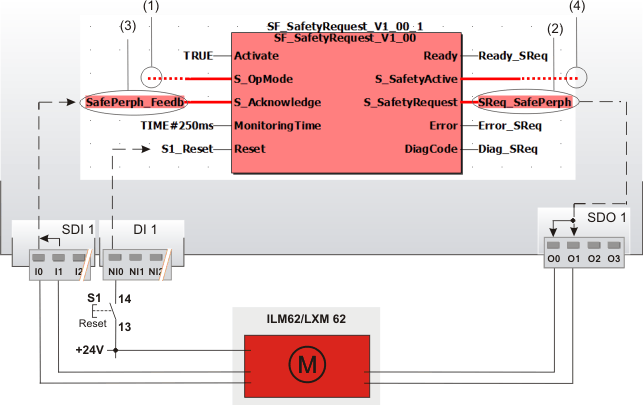
This example shows the exemplary use of the safety-related SF_SafetyRequest function block in case of request and feedback of the safety-related function "safely limited speed" (SLS) of a safety-related drive.
The function block is perpetually activated by the TRUE constant at the Activate input. Reset button S1 is connected to the input NI0 of the standard input device DI 1.
The relevant inputs and outputs are connected as follows:
The S_OpMode input of the SF_SafetyRequest function block is directly connected to the S_Mode0Sel enable signal of the upstream SF_ModeSelector function block. The request for the safety-related function (of the evaluated mode selector switch) is consequently the selection of the operating mode 0. In our example this is the commissioning or maintenance mode in which the drive is operated with safely limited speed. (See digit (1) in the graphic below.)
The S_SafetyRequest output is connected to the global I/O variable SReq_SafePerph, which in turn is assigned to the output O0 of the safety-related output device SDO 1 (see (2) in the graphic below). The safety-related drive module is connected to the output terminals O0 and O1 using two channels here.
The feedback signal for confirming the selected operating mode of the safety-related drive is connected as two-channel signal to the inputs I0 and I1 of the safety-related input device SDI 1. The signal evaluated for equivalence by the safety-related input device is assigned to the global I/O variable SafePerph_Feedb and connected to the S_Acknowledge input of the SF_SafetyRequest function block for evaluation ((3) in the graphic).
The S_SafetyActive enable output is connected to the S_SafetyActive input of the SF_EnableSwitch function block (see (4)). If the requested safely limited speed is confirmed by the safety-related drive at the S_Acknowledge input within the monitoring time specified at MonitoringTime, the S_SafetyActive enable output switches to SAFETRUE and thus signals the safe mode to the subsequent SF_EnableSwitch function block.
Further Information
Refer to the detailed description and notes in the topic entitled "Details of the application example".

Detailed information
Additional information is available in the following sections: