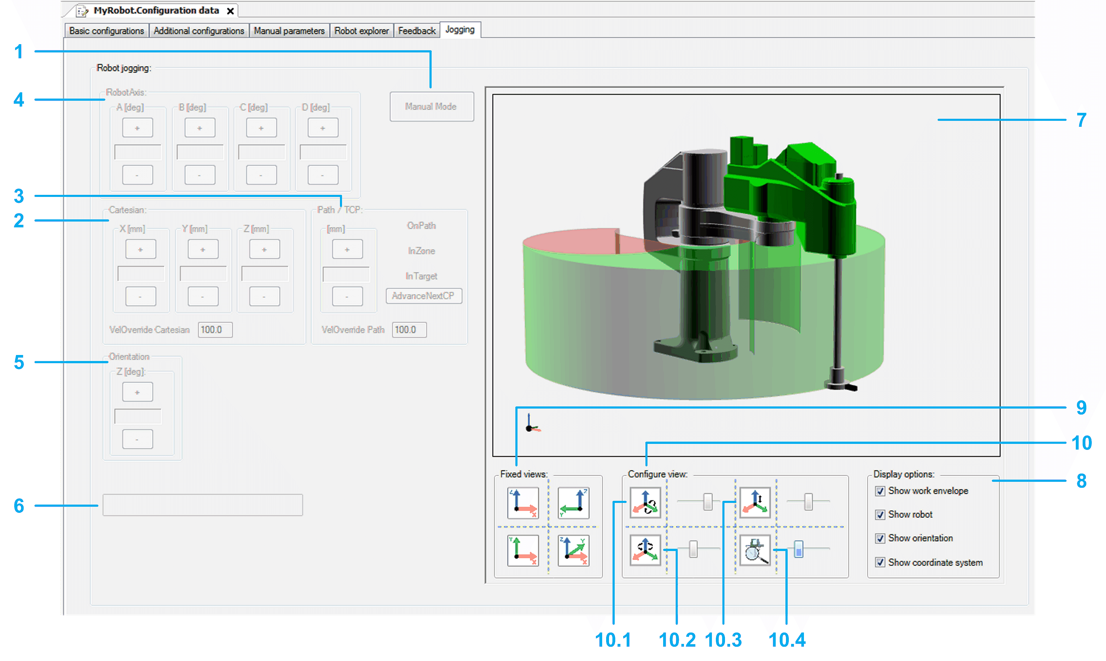
The Jogging tab:
oHelps you to move the robot manually.
oDisplays the robot movements in a 3D visualization.
|
|
|
UNINTENDED MOVEMENT OF THE AXIS |
|
oBefore commissioning, ensure the proper functioning of the functional safety equipment. oBefore and during commissioning, ensure that you can stop axis movements at any time using functional safety equipment (limit switch, emergency stop). |
|
Failure to follow these instructions can result in death, serious injury, or equipment damage. |
NOTE: If the robot application is offline or the robot module is not called within the application, the jogging controls are disabled.

oThe left side of the Jogging tab (items 1 to 6) helps you to process the jogging functionality of the robot.
oThe right side of the Jogging tab (items 7 to 10) displays a visualization of the robot. The visualization can be configured (display options and views).
Jogging functionality
|
1 |
Manual Mode Click this button to enable the jogging mode of the robot. If the manual mode demand is accepted, the background color of the button switches to green. Now you can move the robot step-by-step with the buttons of the various jogging modes: oJogging along the Cartesian coordinate system (Cartesian) oTCP (Tool Center Point) jogging on path (Path / TCP) oJogging along the robot axes by controlling the corresponding drives (Robot Axis) oJogging the orientation around Cartesian Z of the coordinate system (Orientation) |
|
2 |
Cartesian Click the buttons (positive / negative) to move (jog) the TCP (Tool Center Point) along the axes of the Cartesian coordinate system. The displayed cartesian parameters depend on the configuration of ET_WorkingPlane (refer to Robotic Library Guide). |
|
3 |
Path / TCP Click the buttons (positive / negative) to move (jog) the TCP (Tool Center Point) along a connected path (if a connected path is available). For status information on the TCP movement, refer to the feedback properties xOnPath, xInZone, and xInTarget (refer to Robotic Library Guide). |
|
4 |
Robot Axis Click the buttons (positive / negative) to move (jog) along the robot axes by controlling the corresponding drives. |
|
5 |
Orientation Click the buttons (positive / negative) to move (jog) the orientation around Cartesian Z of the coordinate system. |
|
6 |
List box Displays the pending hardware and software limits. |
Configuring the visualization
|
7 |
Robot 3D visualization Shows the movement of the robot, particularly the TCP (Tool Center Point) movement within the working plane. |
|
8 |
Display options Activate the check boxes to define what is displayed in the Robot 3D visualization (work envelope, robot, orientation, coordinate system). |
|
9 |
Fixed views Click one of the four buttons to select a fixed default view of the robot. |
|
10 |
Configure view Move the sliders to configure the rotation, translation, and zoom of the displayed robot. 10.1 Rotation around Y-axis 10.2 Rotation around Z-axis 10.3 Translation in direction of Z-axis 10.4 Zoom |