The function block calculates the PI response for set point i_rSp and outer loop actual value i_rActValPI. This PI response added to pre control value i_rPreCtrlVal and limited by maximum and minimum threshold inputs, serves as set point to inner PID loop.
The inner loop calculates a PID response with i_rActValPID as the inner loop actual value.
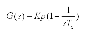
This equation shows the transfer function of PI element:

Where:
Kp = Proportional gain
Tn = Integral time
This equation shows the transfer function of PID element:

Where
Kp = Proportional gain
Tn = Integral time
Automatic mode:
Td = Derivative time
Tv = Filter time
The PI loop and the PID loop can be setup individually in manual modes using input pins i_xManModePI and i_xManModePID respectively. In manual mode, PI loop output and PID loop outputs are substituted by values at input pins i_rManValPI and i_rManValPID respectively.
This figure shows the transfer function for FB_PI_PID function block

This figure shows the timing diagram for the FB_PI_PID function block

An invalid parameter at the function block inputs results in a detected error and a corresponding detected error ID is generated.
During the error detected state the output values are set to zero.
Detected error can be reset only through rising edge of i_xErrRst input.
The output q_xBusy is TRUE whenever the function block is enabled and when there is no detected error.