This figure shows the pin diagram of the FB_PWM function block:
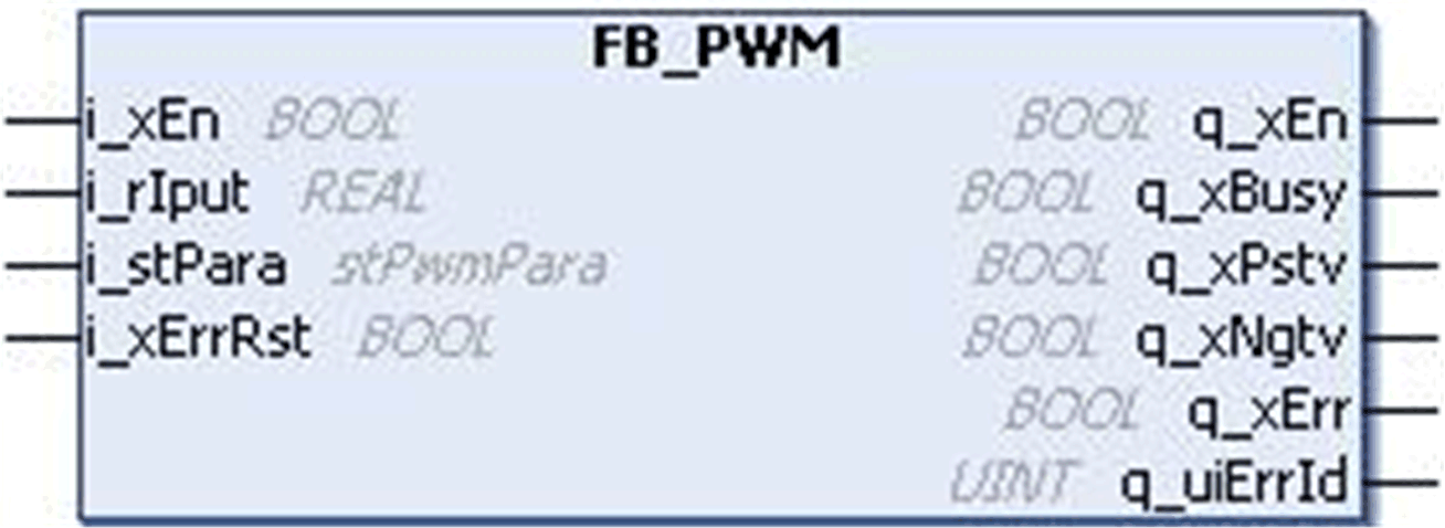
The FB_PWM function block is developed to provide a PWM output based on the input parameter.
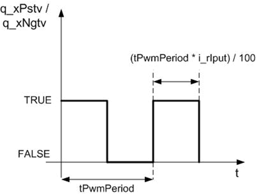
The PWM output is generated with defined ON time and OFF time as per the input shown in the first timing diagram below.
With reference to the second timing diagram:
oIf i_rIput is a positive value, then the PWM output is available in the q_xPstv. The input i_rIput should be in a range of -100 to 100. The ON time of PWM is determined as given below: PWM ON time = (i_rIput x tPwmPeriod) / 100.
oIf i_rIput is a negative value, then the PWM output is available in q_xNgtv.
oIf i_rIput is greater than 100, then it is limited to 100 and if i_rIput is less than –100, then it is limited to –100.
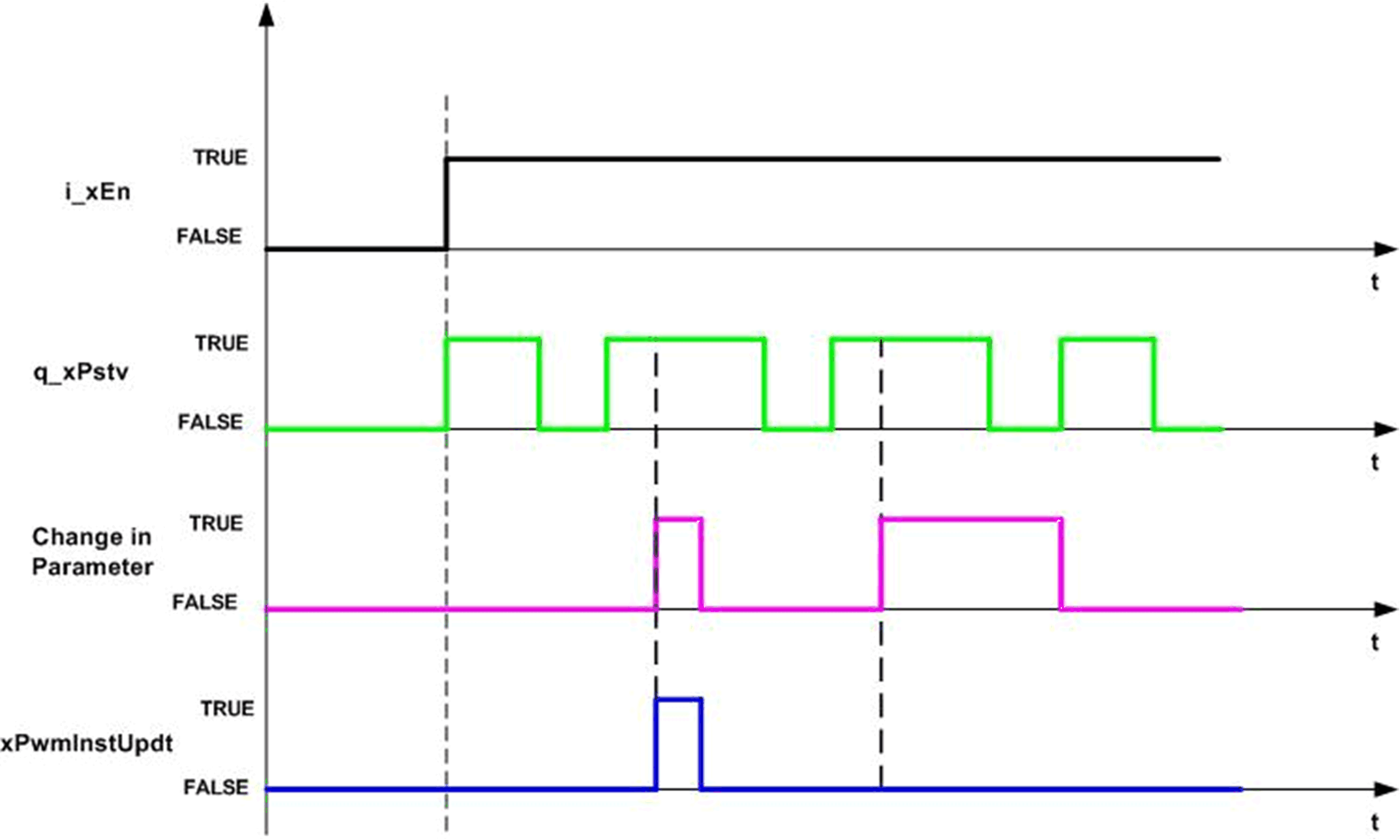
oIf i_xPwmInstUpdt is TRUE, the change in input parameter is updated in the current PWM cycle itself as shown in the timing diagram.
oIf i_xPwmInstUpdt is FALSE, the change in input is updated only during a start of a new PWM cycle.
The q_xEn is TRUE as long as the input i_xEn is TRUE, regardless of detected error.
This figure shows the timing diagram for FB_PWM calculation:
This figure shows the timing diagram for FB_PWM function block:
Example with a Frequency Signal
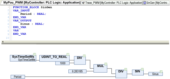
The program creates a Sinus signal at a certain period (5 seconds/0.2 Hz). This Sinus signal is the input of the FB_PWM.
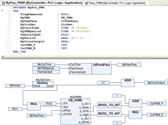
Definition of the SinGen function block:
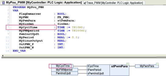
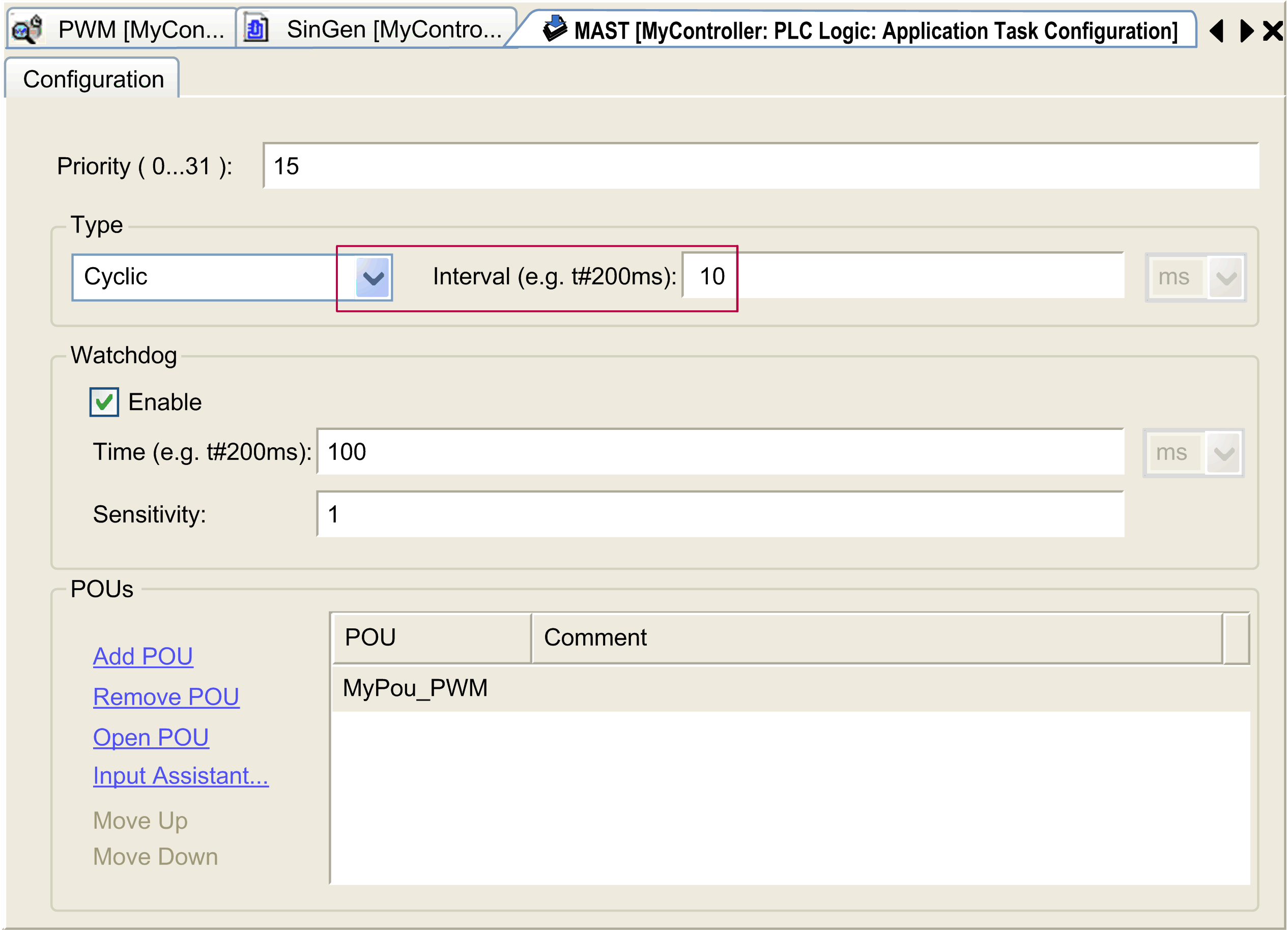
The input stPwmPara.tCycTime of the FB_PWM function block must have exactly the same value as the period of the POU in the MAST, here 10 milliseconds (see the red bordered area).
The result of the previous POU:
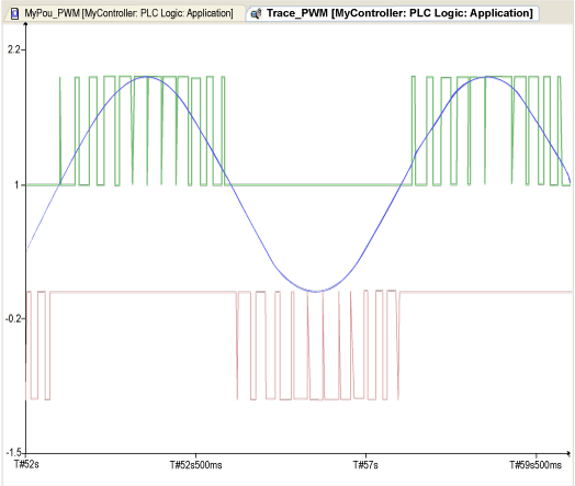
Blue i_rIput sinus signal at 0.2 Hz (function block My_Filter_PT1_1).
Green q_xPstv (an offset is added for the trace).
Red q_xNgtv (the signal is inversed for the trace).
An invalid parameter at the function block inputs results in detected error and corresponding detected error ID is generated.
During detected error state, the output is set to zero.
The detected error can be reset only through rising edge of i_xErrRst input. The output q_xBusy is TRUE whenever the function block is enabled and there is no detected error.