Frequency_Multiplier Function Block
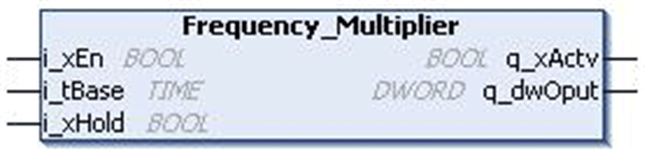
This figure shows the pin diagram of the Frequency_Multiplier function block:
The Frequency_Multiplier function block implements 32 blinkers represented by the bits of output.
On every rising edge of enable signal, the blinker output starts with zero. The lowest bit changes its state after a time base period. The second bit blinks with half the frequency of the initial one. The third bit blinks with half the frequency of the second one and so on, until enable signal is reset. If i_xHold input is set, then current state of blinkers is Hold. If blinkers of type BOOL are required the function block DWORD_AS_BIT (Util Library) can be used.
The output is reset on the rising edge of Enable input.
Frequencies (Enable = TRUE, Timebase = t#100ms, Hold = FALSE)
DWORD_AS_BIT (Input = Frequency ouput)
DWORD_AS_BIT.B00 is blinking with 100 ms
DWORD_AS_BIT.B01 is blinking with 200 ms
DWORD_AS_BIT.B02 is blinking with 400 ms
This table describes the input pins of the Frequency_Multiplier function block:
|
Input |
Data Type |
Description |
|---|---|---|
|
i_xEn |
BOOL |
TRUE: FB enabled FALSE: Disabled |
|
i_tBase |
TIME |
Time period Range: 1...4294967295 ms (≥ cycle time of controller) |
|
i_xHold |
BOOL |
TRUE: Active FALSE: Disabled |
This table describes the output pins of the Frequency_Multiplier function block:
|
output |
Data Type |
Description |
|---|---|---|
|
q_xActv |
BOOL |
TRUE: FB enabled FALSE: Disabled |
|
q_dwOput |
DWORD |
Output status Range: 0...4294967295 |