The function block FB_PID provides a PID controller.
The following graphic shows a pin diagram of the function block FB_PID:

The main algorithm is represented by the following flow chart:

The main algorithm is calculated as:

While a derivative time constant of Td=0 will disable the derivative branch of the PID controller, a proportional gain Kp of 0 is prohibited. This would result in a gain of 100%.
Setting the integral time constant Ti=0 will switch to an alternate calculation rule:

This would center the analog output signal which is in a range [0..10000].
The measured value can be converted into a parametrized range. This new range will then be applied to the setpoint as well as to the measure alarm levels.
In each case, the output is in a range [0..10000] but can be limited.
The table describes the input variables of the function block in the TwidoEmulationSupport library:
|
Input |
Data Type |
Description |
|---|---|---|
|
i_iMeasure |
INT |
Control variable [1..10000] |
|
i_iSetpoint |
INT |
Controller setpoint [1..10000] or [configured min..configured max] |
|
i_etOpMode |
ET_PidOpMode |
PID / PI - in case of PID it can be overwritten by etCorrectorType for compatibility purposes. |
|
i_xMeasConversion |
BOOL |
Activates the conversion of measured values to the given bounds from [0..10000] to [i_iConversionMin..i_iConversionMax]. |
|
i_iConversionMin |
INT |
Conversion of the minimum value. |
|
i_iConversionMax |
INT |
Conversion of the maximum value. |
|
i_xMeasAlarm |
BOOL |
Activates the measured value range alarms. |
|
i_iAlarmHigh |
INT |
High alarm threshold value for q_iAnalogOutput. |
|
i_iAlarmLow |
INT |
Low alarm threshold value for q_iAnalogOutput. |
|
i_iKp |
INT |
Proportional gain factor |
|
i_iTi |
INT |
Integral time constant |
|
i_iTd |
INT |
Derivative time constant (is ignored in case of PI) |
|
i_xDirectOutput |
BOOL |
TRUE: direct action FALSE: reverse action |
|
i_xLimitOutput |
BOOL |
Activates the output limitation. |
|
i_iLimitMin |
INT |
Output lower limit |
|
i_iLimitMax |
INT |
Output upper limit |
|
i_iPWMPeriod |
INT |
PWM signal |
The table describes the output variables of the function block in the TwidoEmulationSupport library:
|
Output |
Data Type |
Description |
|---|---|---|
|
q_iAnalogOutput |
INT |
Controller output to be digital to analog converted [1..10000] |
|
q_rDutyCycleOutput |
REAL |
Reduced to a value [0..1] which can be assigned to a PWM module manually. |
|
q_xPWM |
BOOL |
Software generated PWM output |
|
q_xMeasureValueLowAlarm |
BOOL |
Monitoring of the control variable. Is set to 1, if the low alarm level is underrun. |
|
q_xMeasureValueHighAlarm |
BOOL |
Monitoring of the control variable. Is set to 1, if the high alarm level is exceeded. |
|
q_etPidDiag |
ET_PidDiag |
Diagnostic code from the PID controller |
|
q_sMsg |
STRING |
Diagnostic message |
The PID block configuration in EcoStruxure Machine Expert - Basic provides the additional parameter sampling period (in the PID tab of the PID Assistant). The sampling period is the cycle time of the task which executes the PID block. To help ensure that the signal at q_xPWM is generated properly, the configured i_iPWMPeriod must be a multiple of the sample time. A PWM period of 0 deactivates the signal generation.
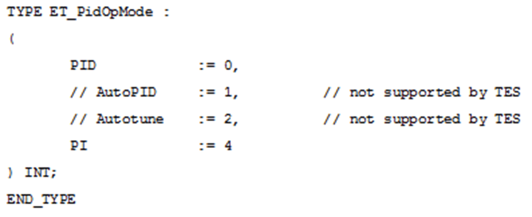
The i_etOpMode input is of the type:

The i_etPidDiag output is of the type:
