Note
Refer to the general description for information about the following tabs of the device editor.
Only in the case of special features is there an additional help page for the specific device editor.
If the "<device name> Parameters" tab is not shown, then enable the Show generic device configuration editors option in the CODESYS options (Device editor category).
A Modbus network consists of a Modbus master and one or more Modbus slaves. A maximum of 32 slaves can be attached to a master. The Modbus devices can be linked via serial port or Ethernet.
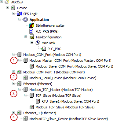
Modbus devices, linked via serial port of the device in use Modbus COM Port
(1): The CODESYS runtime acts as a Modus master.
(2): The CODESYS runtime acts as a Modus slave. This Modbus slave is named "Modbus Device" in the following text.
For Modbus serial, the operating type "Modbus RTU" is supported.
Modbus devices, linked in an Ethernet network using the device Ethernet Adapter.
(3): The CODESYS runtime acts as a Modus master (client).
A Modbus TCP slave can also act as a gateway for serial Modbus slaves.
(4): The CODESYS runtime acts as a Modbus slave (server).
You can configure communication parameters in the Modbus configuration pages and then create Modbus channels. A Modbus channel includes a single Modbus command (read/write data) as well as the respective I/O channels.
See also
If there are no specific controller restrictions, then the master generally supports the following function codes:
FC01 Read Coils
FC02 Read Discrete Inputs
FC03 Read Holding Registers
FC04 Read Input Registers
FC05 Write Single Coil
FC15 Write Multiple Coils
FC06 Write Single Register
FC16 Write Multiple Registers
FC23 Read/Write Multiple Registers
Access to Modbus devices from the application
If you insert a Modbus device in the device tree, then an instance of the respective function block is created automatically. The variable name of the instance corresponds to the name of the device in the device tree. Using this function block, you can access the functions of the Modbus devices from the application. For example, via the outputs of this function block, you can query the status of the last Modbus command (whether successful or not).
You will find the device instance in the <device name> IEC Objects tab of the corresponding device editor. Refer also to the description of this dialog.
Note
For Modbus masters (RTU/TCP)
In addition to the Modbus commands defined in the configurator (and the implicitly generated I/O mapping), programmed Modbus requests can also be executed using the block ModbusRequest.