In CODESYS, the alarm management is a powerful object for creating and managing alarms. You can group alarms and set the acknowledgment behavior individually. The alarm display can also be customized in the visualization.
The Alarm table and Alarm banner visualization elements are available for displaying and processing alarms. The alarm table lists the alarm texts. The alarm banner is a simplified version of the alarm table. It visualizes a single alarm only. However, by adding scroll elements you can allow for switching the display from active alarm to another active alarm.
See also
Requirement: In your project, alarms are defined in alarm groups and they are assigned to an alarm class. The following statement is based on the example that is presented in the section "Configuring alarm management".
Open the visualization editor.
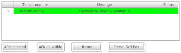
Drag the Alarm table element from the Alarm manager group to the visualization editor.
⇒ The Alarm table visualization element is visible in the editor.
In Alarm configuration / Alarm groups, define the alarm groups to be visualized. Click into the value field.
⇒ The Alarm Group Selection dialog opens.
Clear the All check box and select the PartsDeficit alarm group. Add the group to the selected alarm groups by clicking the  button.
In Alarm configuration / Alarm classes, define the alarm classes to be visualized. Click into the value field.
⇒ The Alarm Group Selection dialog opens.
Clear the All check box and select the PartsDeficit alarm class. Add the alarm class to the selected alarm classes by clicking the button.
Add an additional column. Click the Columns / Create new button.
⇒ CODESYS adds the column [2] to the properties. The Symbol column is added to the table.
Select data type State for column [2].
⇒ The default column heading State is shown in the table.
Name the Column heading column "Status".
Specify the appearance of the selected table cell. Set the Selection / Selection color to Green.
In the Control variables / Confirm selection property, specify the variable bQuitAlarm for confirming messages.
Adjust the other properties to their requirements. Refer to the visualization element "Alarm table" for a complete description of the properties.
See also
Inserting elements to the alarm acknowledgment
In CODESYS, predefined buttons are available for controlling the alarms in an alarm table.
Requirement: An Alarm table element is located in the visualization.
Select the visualization element in the editor.
Execute the command Visualization ‣ Insert elements for acknowledging alarms .
⇒ The Alarm table wizard dialog opens.
Click OK to accept all settings.
⇒ Four buttons are added for controlling the alarm table.
See also
Requirement: In your project, alarms are defined in alarm groups and they are assigned to an alarm class. The following statement is based on the example that is presented in the section "Configuring alarm management".
The alarm banner displays an active alarm in online mode. If there are multiple active alarms, filtering takes place by means of the filter criteria set in the alarm banner (newest for filter criterion "Priority" and most important for filter criterion "Newest"). See the instructions below for adding scroll elements in order to switch the display between multiple alarms.
Open the visualization editor.
Drag the Alarm banner element from the Alarm manager group to the visualization editor.
⇒ The Alarm banner visualization element is visible in the editor.
In Alarm configuration / Alarm groups, define the alarm groups to be visualized. Click into the value field.
⇒ The Alarm Group Selection dialog opens.
Clear the All check box and select the PartsDeficit alarm group. Add the group to the selected alarm groups by clicking the button.
In Alarm configuration / Alarm classes, define the alarm classes to be visualized. Click into the value field.
⇒ The Alarm Group Selection dialog opens.
Clear the All check box and select the PartsDeficit alarm class. Add the alarm class to the selected alarm classes by clicking the button.
Set the Alarm configuration / Filter criterion property to Newest.
⇒ In online mode, the newest alarm message is always shown.
Add an additional column. Click the Columns / Create new button.
⇒ CODESYS adds the column [2] to the properties. The Symbol column is added to the table.
Select data type State for column [2].
⇒ The default column heading State is shown in the table.
In the Confirmation variable property, specify the variable bQuitAlarm for confirming messages.
See also
Adding elements for scrolling the active alarms
Elements can be added to an alarm banner for switching the display between the individual active alarms. You can control the scrolling with visu-local variables or application variables.
Select the added "Alarm banner" visualization element. Select the Add elements for controlling alarms command in the context menu.
⇒ The Alarm Banner Wizard opens.
Select the element type for the scroll elements: Button or Rectangle.
Activate the action(s) for which a control element should be added: Scroll to next alarm, Scroll to previous alarm.
Specify a Boolean variable that gets the value TRUE when multiple active alarms are present. If you have already configured a project variable in the element properties, then it is also specified here in the wizard. Otherwise CODESYS automatically creates the visu-local variable xMultipleAlarmsActive.
In the next step, check the configuration of the element properties of the extended alarm banner.
Select the alarm banner element and look at the section Handling of multiple active alarms in the Properties view. You have two options:
Option 1: The display should switch automatically. Activate the property Switch automatically.
⇒ Now, in Every N seconds you define the time interval after which the display in the alarm banner in online mode should switch to the next alarm.
Option 2: The display should be controlled by means of the application. Deactivate the property Switch automatically.
⇒ Switching between the active alarms can be controlled by two variables. By default, xNext and xPrev are created for scrolling to the next or previous alarm. You can replace these variables with custom your own defined application variables.