|
|
|
SPRING LOADED MECHANISM |
|
Do not release the spring clip mechanism near your face. |
|
Failure to follow these instructions can result in injury or equipment damage. |
|
NOTICE |
|
EQUIPMENT DAMAGE |
|
Keep this product stabilized in the panel cutout while you are installing or removing the spring clips. |
|
Failure to follow these instructions can result in equipment damage. |
|
Step |
Action |
|---|---|
|
1 |
Place this product on a clean and level surface with the screen facing down. |
|
2 |
Check that this product’s gasket is seated securely into the bezel’s groove, which runs around the perimeter of the display frame. NOTE: Always use the installation gasket, since it absorbs vibration in addition to repelling water. For the procedure on replacing the installation gasket, refer to Replacing the Installation Gasket. |
|
3 |
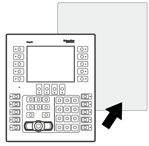
Based on this product's panel cutout dimensions, open a mount hole on the panel and attach this product to the panel from the front side. 
|
|
4 |
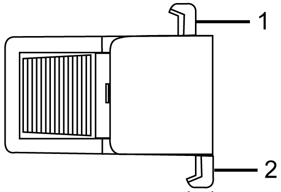
Press the spring clip hooks into the insertion slots on this product. Adjust the spring clips for the panel thickness by turning it over: oPosition 1 1.5 mm (0.059 in) ≤ panel thickness ≤ 4 mm (0.157 in). oPosition 2 4 mm (0.157 in) ≤ panel thickness ≤ 6 mm (0.236 in). 
Side of the spring clip 1 Hook for position 1 2 Hook for position 2 |
|
5 |
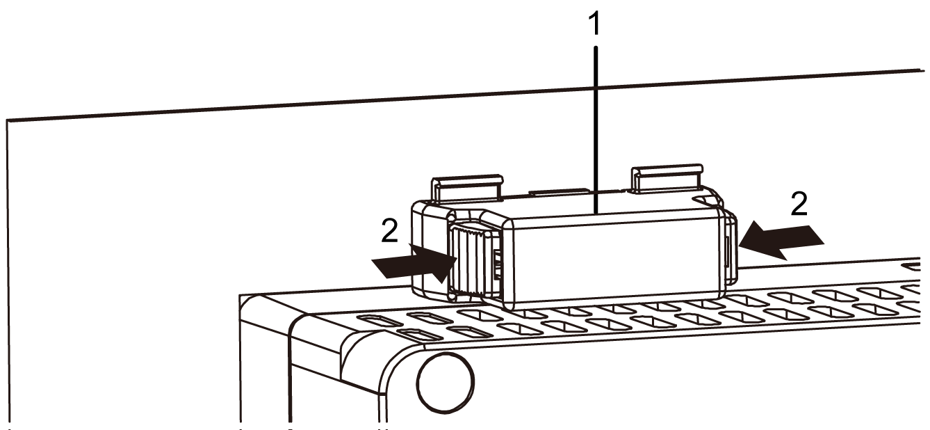
Lock the spring clips by simultaneously pressing the top and bottom of the clip. 
1 Spring clip 2 Click Number of spring clips HMIGK2310 oTop - 2, Bottom - 2, Right - 3, Left - 3 HMIGK5310 oTop - 3, Bottom - 3, Right - 3, Left - 3 |
|
NOTICE |
|
EQUIPMENT DAMAGE |
|
Keep this product stabilized in the panel cutout while you are installing or removing the spring clips. |
|
Failure to follow these instructions can result in equipment damage. |
|
Step |
Action |
|---|---|
|
1 |
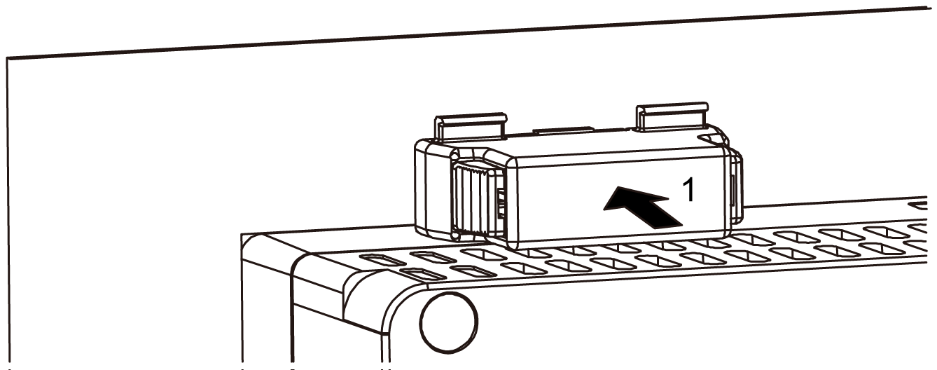
Remove the spring clips. First unlock the clips by pressing on the back of the clip until you hear a click. 
1 Click |
|
2 |
Remove this product slowly from the panel. |