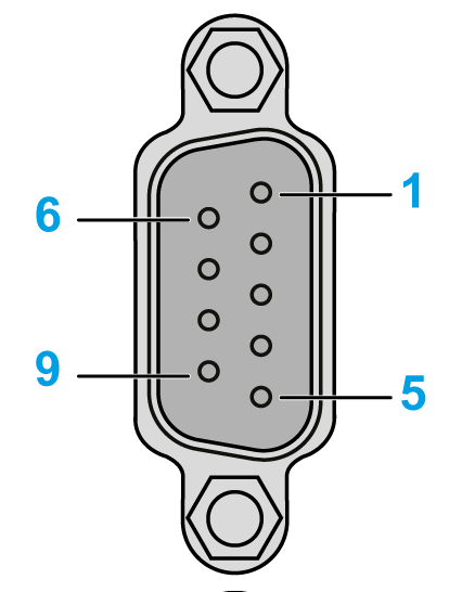
Specifications of Serial Interface COM1
NOTE: For information on how to connect controllers and other types of equipment, refer to the corresponding device driver manual of your screen editing software.
|
|
|
LOSS OF COMMUNICATION |
|
oAll connections to the communication ports must not put excessive stress on the ports. oSecurely attach communication cables to the panel or cabinet. oUse only D-Sub 9-pin cables with a locking system in good condition. |
|
Failure to follow these instructions can result in injury or equipment damage. |
The serial port is not isolated. The SG (signal ground) and FG (frame ground) terminals are connected inside the panel.
HMIGTO5310 / HMIGTO5315: D-Sub 9-pin plug connector via a RS-232C cable.
|
Pin Connection |
Pin No. |
RS-232C |
||
|---|---|---|---|---|
|
Signal Name |
Direction |
Meaning |
||

|
1 |
CD |
Input |
Carrier Detect |
|
2 |
RD(RXD) |
Input |
Receive Data |
|
|
3 |
SD(TXD) |
Output |
Send Data |
|
|
4 |
ER(DTR) |
Output |
Data Terminal Ready |
|
|
5 |
SG |
- |
Signal Ground |
|
|
6 |
DR(DSR) |
Input |
Data Set Ready |
|
|
7 |
RS(RTS) |
Output |
Request to Send |
|
|
8 |
CS(CTS) |
Input |
Send possible |
|
|
9 |
CI(RI)/VCC |
Input– |
Called Status Display +5 V±5% Output 0.25 A*1 |
|
|
Shell |
FG |
– |
Frame Ground (Common with SG) |
|
NOTE: *1 You can switch pin number 9 between RI and VCC via software.
|
NOTICE |
|
EQUIPMENT DAMAGE |
|
Use only the rated current. |
|
Failure to follow these instructions can result in equipment damage. |