Follow these instructions when supplying power to the panel.
oWhen the functional ground (FG) terminal is connected, be sure the wire is grounded. Not grounding the panel can result in excessive Electromagnetic Interference (EMI). Grounding is required to meet EMC level immunity.
oThe shield ground (SG) and FG terminals are connected internally in the panel.
oDisconnect the power before wiring the panel's power terminals.
oThe panel uses only 24 Vdc power. Using any other level of power can damage both the power supply and the panel.
oSince the panel is not equipped with a power switch, be sure to connect a power switch to the panel’s power supply.
oBe sure to ground the panel's FG terminal.
oMake sure the ground wire is either the same or heavier gauge than the power wires.
oDo not use aluminum wires in the power supply's power cord.
oIf the ends of the individual wires are not twisted correctly, the wires may create a short circuit. To avoid this, use D25CE/AZ5CE cable ends.
oWherever possible, use wires that are 0.75 to 2.5 mm2 (AWG 18 - 12) for the power cord, and twist the wire ends before attaching the terminals.
oThe conductor type is solid or stranded wire.


|
Connection |
Wire |
|---|---|
|
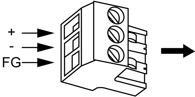
+ |
24 Vdc |
|
- |
0 Vdc |
|
FG |
Grounded terminal connected to the panel chassis. |
|
Step |
Action |
|---|---|
|
1 |
Remove the power cord from the power supply. |
|
2 |
Remove the power plug from the panel. |
|
3 |
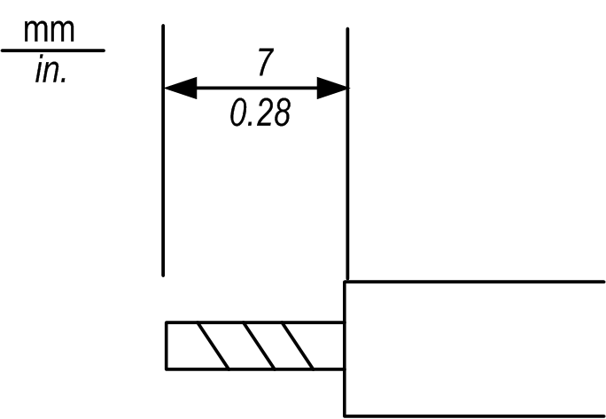
Remove 7 mm (0.28 in.) of the vinyl cover off the ends of the power cord wires. |
|
4 |
If using stranded wire, twist the ends. Tinning the ends with solder reduces risk of fraying and ensures good electrical transfer. |
|
5 |
Connect the wires to the power plug by using a flat-bladed screwdriver (size 0.6 X 3.5). |
|
6 |
Tighten the mounting screws using the defined torque: 0.5...0.6 Nm (5...7 lb-in). |
|
7 |
Replace the power plug onto the power connector. |
NOTE:
oDo not solder the wire directly to the power receptacle pin.
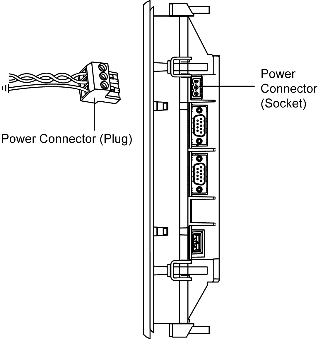
oThe power supply cord should meet the specification shown above. Be sure to twist the power cords together, up to the power plug, for EMC cancellation (see illustration as shown below).
Example of Power Cord Connection
The following illustration shows a connection example of the power cord:
