System and I/O Diagnostic LEDs
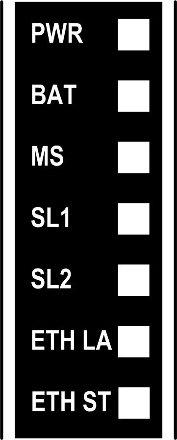
The following illustration shows the system LEDs on the front panel display:

NOTE: Ethernet LEDs ETH LA and ETH ST are present only on the system LED display of the TM218LDAE24DRHN and TM218LDAE40DRPHN controllers.
The table below describes the status of the system LEDs for the M218 controllers:
|
Label |
Function type |
Color |
Status |
Description |
||
|---|---|---|---|---|---|---|
|
States1 |
Prg port communication |
Application execution |
||||
|
PWR |
Power |
Green |
On |
Indicates that power is applied. |
||
|
Off |
Indicates that power is removed. |
|||||
|
BAT |
Battery |
Red |
On |
Indicates that the RTC battery needs to be replaced. |
||
|
Flashing |
Indicates that the battery charge is low. |
|||||
|
MS |
Main status |
Green/Red |
Flashing green/Red |
BOOTING |
NO |
NO |
|
Red flash |
INVALID OS |
Restricted |
NO |
|||
|
1 green flash |
No application |
Yes |
NO |
|||
|
Green on |
RUNNING |
Yes |
Yes |
|||
|
3 green flashes |
RUNNING with breakpoint |
Yes |
Restricted |
|||
|
Flashing green |
STOPPED |
Yes |
NO |
|||
|
Rapid flashing red |
Event state HALT with detection of an application error |
Yes |
NO |
|||
|
Red on |
Internal error detected |
NO |
NO |
|||
|
Off |
Power removed |
NO |
NO |
|||
|
Green with 1 red flashing |
RUNNING with detection of an external error |
Yes |
Yes |
|||
|
Flashing green with 1 red flash |
STOPPED with detection of an external error |
Yes |
NO |
|||
|
SL1 |
Serial link 1 |
- |
- |
|||
|
SL2 |
Serial link 2 |
- |
- |
|||
|
ETH LA |
ETH activity |
- |
- |
|||
|
ETH ST |
ETH status |
- |
- |
|||
1 For more information about the controller state description, refer to the programming guide.
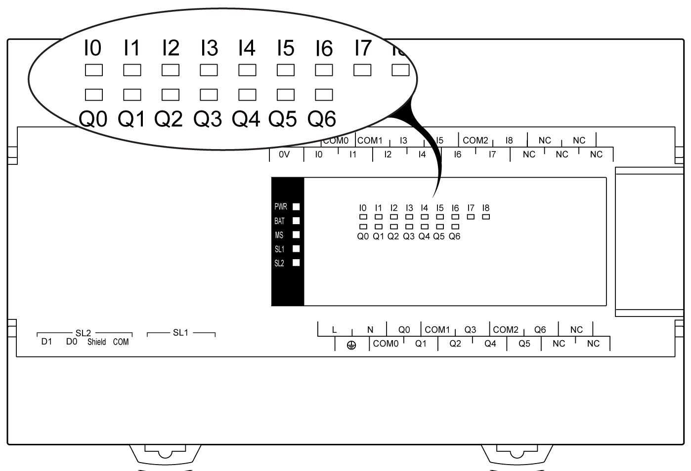
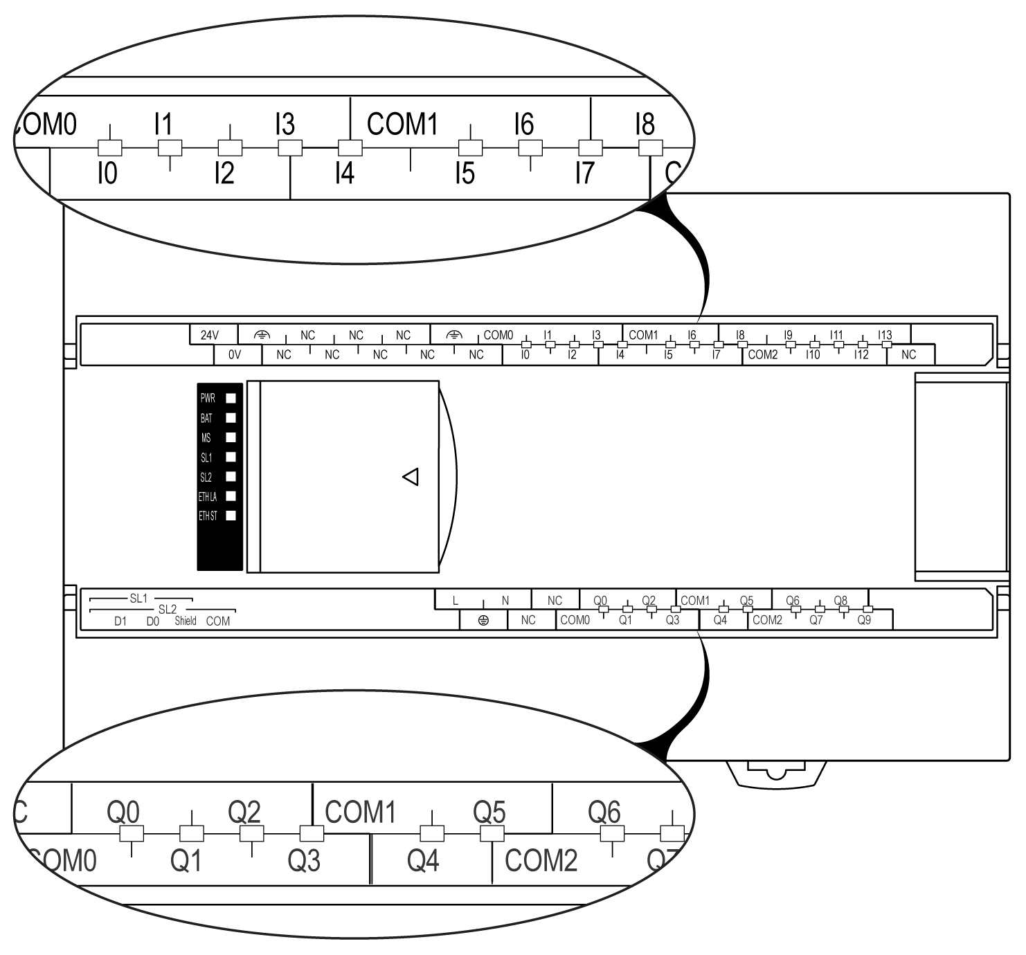
Depending on the M218 controller model, I/O LEDs are located:
oon the center of the controller’s front panel, or
owithin the I/O terminal block labels of the controller
The illustration below shows the front panel center location of the I/O status LEDs:

The illustration below shows the I/O terminal block label location of the I/O status LEDs:

For each input and output, the LED displays the status of the I/O, not the frequency of the I/O signal:
|
Function Type |
Color |
Status |
Description |
|---|---|---|---|
|
Digital input |
Green |
On |
Indicates that the input state is active |
|
Off |
Indicates that the input state is not active |
||
|
Digital output |
Green |
On |
Indicates that the output state is active |
|
Off |
Indicates that the output state is not active |
NOTE: If the frequency of the digital output used as a PTO is less than 46 Hz, the corresponding output LED willl be off.