See Output Management for more information on managing outputs.
|
|
|
FIRE HAZARD |
|
oUse only the correct wire sizes for the current capacity of the I/O channels and power supplies. oFor relay output (2 A) wiring, use conductors of at least 0.5 mm2 (AWG 20) with a temperature rating of at least 80 °C (176 °F). oFor common conductors of relay output wiring (4 A), or relay output wiring greater than 2 A, use conductors of at least 1.0 mm2 (AWG 16) with a temperature rating of at least 80 °C (176 °F). |
|
Failure to follow these instructions will result in death or serious injury. |
|
|
|
UNINTENDED EQUIPMENT OPERATION |
|
Do not exceed any of the rated values specified in the environmental and electrical characteristics tables. |
|
Failure to follow these instructions can result in death, serious injury, or equipment damage. |
The table below describes the characteristics of the M218 controller relay outputs:
|
Characteristic |
Value |
|
|---|---|---|
|
Rated voltage |
24 Vdc, 220 Vac |
|
|
Input range |
5...30 Vdc, 100...250 Vac |
|
|
Rated current |
Maximum 2 A for each point (see de-rating curve below) |
|
|
Current/group (4 points) |
4 A (see de-rating curve below) |
|
|
Inrush values |
Maximum switching voltage |
250 Vac, 30 Vdc |
|
Current/point |
5 A |
|
|
Isolation |
Between channels within same category: |
None |
|
Between channels in different categories: |
1780 Vac / 2500 Vdc |
|
|
Between channels and internal logic: |
1780 Vac / 2500 Vdc |
|
|
Maximum output frequency |
With maximum load |
0.1 Hz |
|
Without load |
5 Hz |
|
|
Contact opening time |
Typically 5 ms |
|
|
Contact closing time |
Typically 2 ms |
|
|
Resistive load |
2 A/point for 24 Vdc/220 Vac |
|
|
Mechanical life |
20 million operation minimum at 25 °C (77 °F) for maximum current and voltage ratings |
|
|
Cable length |
Non-shielded: 150 m (492 ft) |
|
|
Protection against short-circuit |
No |
|
|
Terminal blocks |
Type: Screw, 7.62 mm (0.29 in.) pitch 2 rows are removable |
|
|
NOTE: Refer to Protecting Outputs from Inductive Load Damage for additional information on this topic. |
||
The following illustration shows the Relay Output De-rating curve:
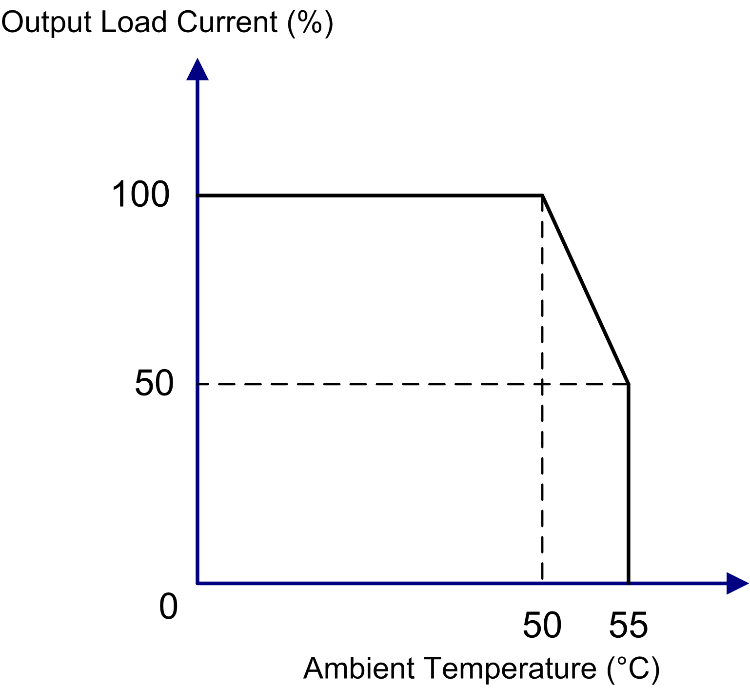
NOTE: 50% de-rating when all the relay outputs are used at 55 °C (131 °F).
The following illustration shows the wiring diagram of the M218 controller’s relay outputs:
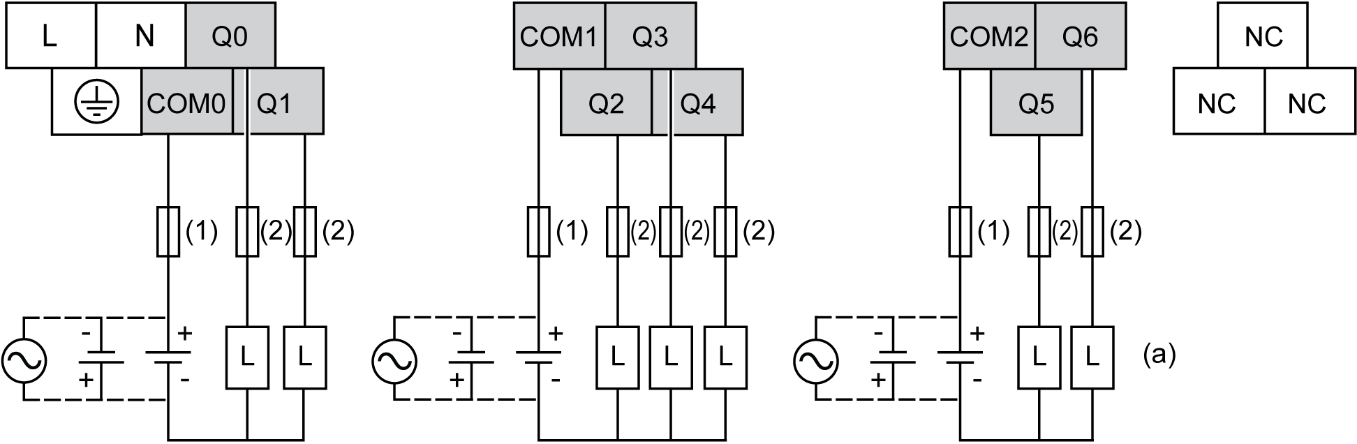
(1) 4 A Type T fuse
(2) 2 A Type T fuse
NC Not Connected (N.C.)
(a) To improve the lifetime of the contacts and to protect from potential inductive load damage, connect:
oa free wheeling diode in parallel to each inductive DC load
oa RC snubber in parallel of each inductive AC load
NOTE: The assigned fuse values have been specified for the maximum current characteristics of the controller I/O and associated commons. You may have other considerations that are applicable based on the unique types of input and output devices you connect, and you should size your fuses accordingly.
|
|
|
UNINTENDED EQUIPMENT OPERATION |
|
Do not connect wires to unused terminals and/or terminals indicated as “No Connection (N.C.)”. |
|
Failure to follow these instructions can result in death, serious injury, or equipment damage. |

