There are 4 different ways to assign the IP address of the controller:
oaddress assignment by DHCP server
oaddress assignment by BOOTP server
ofixed IP address
oaddress assignment using the SetIPAddress function block
NOTE: If the attempted addressing method is unsuccessful, the controller will start using a default IP address derived from the MAC address.
Carefully manage the IP addresses because each device on the network requires a unique address. Having multiple devices with the same IP address can cause unintended operation of your network and associated equipment.
|
|
|
UNINTENDED EQUIPMENT OPERATION |
|
oVerify that there is only one master controller configured on the network or remote link. oVerify that all devices have unique addresses. oObtain your IP address from your system administrator. oConfirm that the IP address of the device is unique before placing the system into service. oDo not assign the same IP address to any other equipment on the network. oUpdate the IP address after cloning any application that includes Ethernet communications to a unique address. |
|
Failure to follow these instructions can result in death, serious injury, or equipment damage. |
NOTE: It is good practice to ensure that your system administrator maintains a record of all assigned IP addresses on the network and subnetwork, and to inform the system administrator of all configuration changes performed.
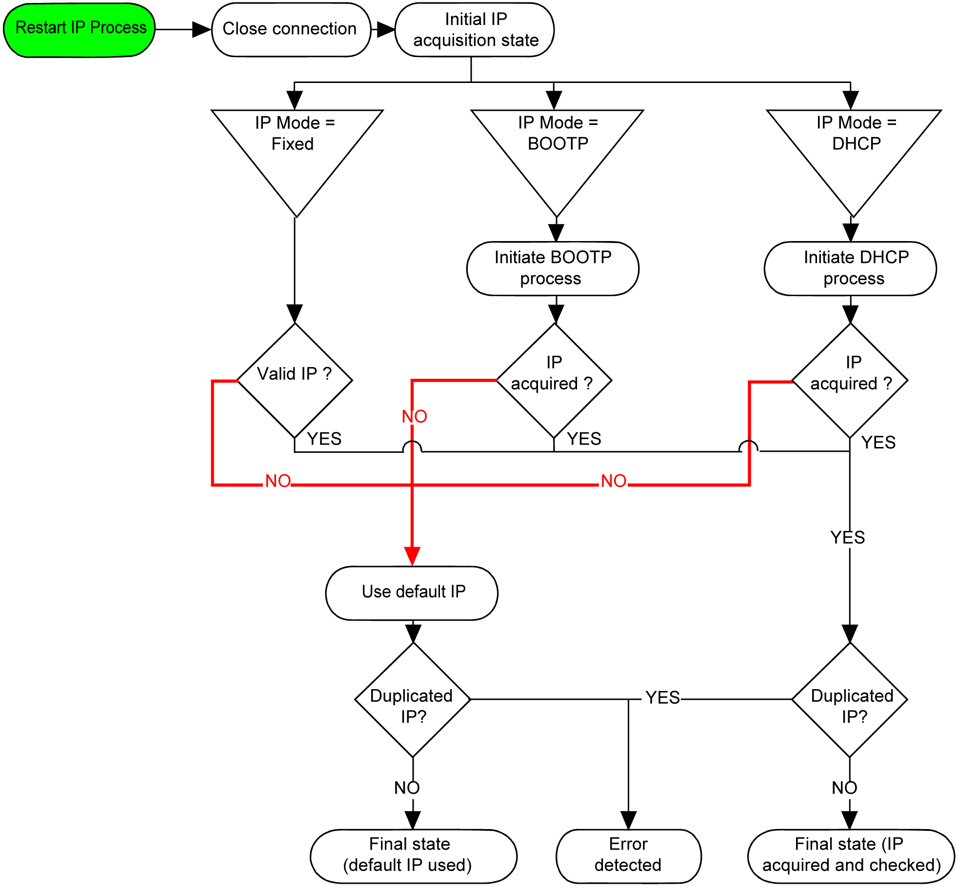
The different types of address systems for the controller are shown in the following diagram:

NOTE: If a device programmed to use the DHCP or BOOTP addressing methods is unable to contact its respective server, the controller will use the default IP address. It will, however, constantly reiterate its request.
The IP process automatically restarts in the following cases:
oController reboot
oEthernet cable reconnection
oApplication download (if IP parameters change)
oDHCP or BOOTP server detection following an unsuccessful addressing attempt.
In the Devices tree, double-click the Ethernet node:

Set the parameters as described in the following table:
|
Element |
Description |
|---|---|
|
Interface Name |
Name of the network interface, maximum 16 characters |
|
Network Name |
Used as device name to retrieve IP address through DHCP, maximum 16 characters |
|
IP Address by DHCP |
IP address is obtained via DHCP. |
|
IP Address by BOOTP |
IP address is obtained via BOOTP. |
|
Fixed IP Address |
IP address, Subnet Mask and Gateway Address are defined by the user. |
|
Ethernet Protocol |
Protocol type used (only supports Ethernet 2) |
|
Transfer Rate |
Transfer rate and direction on the bus are automatically configured. |
The default IP address is based on the device’s MAC address. The first two bytes are 10 and 10. The last two bytes are the last two bytes of the device’s MAC address.
The default subnet mask is 255.0.0.0.
NOTE: A MAC address is always written in hexadecimal format, and an IP address in decimal format. You must convert the MAC address to decimal format.
Example: If the MAC address is 00.80.F4.01.80.F2, the default IP address is 10.10.128.242.
The IP address is linked:
oto a device (known as the host)
oto the network to which the device is connected
An IP address is always coded using 4 bytes.
The distribution of these bytes between the network address and the device address may vary. This distribution is defined by the address classes.
The different IP address classes are defined in the following table:
|
Address Class |
Byte 1 |
Byte 2 |
Byte 3 |
Byte 4 |
||||
|---|---|---|---|---|---|---|---|---|
|
Class A |
0 |
Network ID |
Host ID |
|||||
|
Class B |
1 |
0 |
Network ID |
Host ID |
||||
|
Class C |
1 |
1 |
0 |
Network ID |
Host ID |
|||
|
Class D |
1 |
1 |
1 |
0 |
Multicast address |
|||
|
Class E |
1 |
1 |
1 |
1 |
0 |
Address reserved for subsequent use |
||
The subnet mask is used to address several physical networks with a single network address. The mask is used to separate the sub-network and the device address in the host ID.
The subnet address is obtained by retaining the bits of the IP address which correspond to the positions of the mask containing 1, and replacing the others with 0.
Conversely, the subnet address of the host device is obtained by retaining the bits of the IP address which correspond to the positions of the mask containing 0, and replacing the others with 1.
Example of a subnet address:
|
IP address |
192 (11000000) |
1 (00000001) |
17 (00010001) |
11 (00001011) |
|
Subnet mask |
255 (11111111) |
255 (11111111) |
240 (11110000) |
0 (00000000) |
|
Subnet address |
192 (11000000) |
1 (00000001) |
16 (00010000) |
0 (00000000) |
NOTE: The device does not communicate on its sub-network when there is no gateway.
The gateway allows a message to be routed to a device which is not on the current network.
If there is no gateway, the gateway address is 0.0.0.0.
|
Security Parameters |
Description |
|---|---|
|
EcoStruxure Machine Expert protocol active |
It allows to deactivate the EcoStruxure Machine Expert protocol on Ethernet interfaces. When deactivated, every EcoStruxure Machine Expert request from every device will be rejected, including those from the UDP or TCP connection. This means that no connection is possible on Ethernet from a PC with EcoStruxure Machine Expert, from a XBT target that wants to exchange variables with this controller, from an OPC server, or from Controller Assistant. |
|
Modbus Server active |
It allows to deactivate the Modbus Server of the Logic Controller. That means that every Modbus request to the Logic Controller will be ignored. |