The Modicon M241 Logic Controller has digital inputs embedded:
|
Reference |
Total number of digital inputs |
Fast inputs which can be used as 200 kHz HSC inputs |
Total number of regular inputs |
Regular inputs which can be used as 1 kHz HSC inputs |
|---|---|---|---|---|
|
TM241C••24R TM241C••24T TM241C••24U |
14 |
8 |
6 |
6 |
|
TM241C•40R TM241C•40T TM241C•40U |
24 |
8 |
16 |
8 |
For more information, refer to Input Management.
|
|
|
FIRE HAZARD |
|
oUse only the correct wire sizes for the maximum current capacity of the I/O channels and power supplies. |
|
Failure to follow these instructions will result in death or serious injury. |
|
|
|
UNINTENDED EQUIPMENT OPERATION |
|
Do not exceed any of the rated values specified in the environmental and electrical characteristics tables. |
|
Failure to follow these instructions can result in death, serious injury, or equipment damage. |
The following figure shows the status LEDs for the TM241C••24• controller (the TM241C•40• controllers are similar with 40 LEDs):

|
LED |
Color |
Status |
Description |
|---|---|---|---|
|
0...13 |
Green |
On |
The input channel is activated |
|
Off |
The input channel is deactivated |
The table below describes the characteristics of the M241 Logic Controller with regular inputs:
|
Characteristic |
Values |
||
|---|---|---|---|
|
TM241C••24• |
TM241C•40• |
||
|
Number of regular inputs |
6 inputs (I8...I13) |
16 inputs (I8...I23) |
|
|
Number of channel groups |
1 common line for I8...I13 |
1 common line for I8...I23 |
|
|
Input type |
Type 1 (IEC 61131-2 Edition 3) |
||
|
Logic type |
Sink/Source |
||
|
Input voltage range |
24 Vdc |
||
|
Rated input voltage |
0...28.8 Vdc |
||
|
Rated input current |
5 mA |
7 mA |
|
|
Input impedance |
4.7 kΩ |
||
|
Input limit values |
Voltage at state 1 |
> 15 Vdc (15...28.8 Vdc) |
|
|
Voltage at state 0 |
< 5 Vdc (0...5 Vdc) |
||
|
Current at state 1 |
> 2.5 mA |
||
|
Current at state 0 |
< 1.0 mA |
||
|
Derating |
No derating |
||
|
Turn on time |
50 µs + filter value1 |
||
|
Turn off time |
50 µs + filter value1 |
||
|
Isolation |
Between input and internal logic |
500 Vac |
|
|
Between input terminals |
Not Isolated |
||
|
Connection type |
Removable screw terminal block |
||
|
Connector insertion/removal durability |
Over 100 times |
||
|
Cable |
Type |
Unshielded |
|
|
Length |
Maximum 50 m (164 ft) |
||
|
1 For more information, refer to Integrator Filter Principle |
|||
The table below describes the characteristics of the M241 Logic Controller with fast inputs:
|
Characteristic |
Value |
||
|---|---|---|---|
|
Number of fast transistor inputs |
8 inputs (I0...I7) |
||
|
Number of channel groups |
1 common line for I0...I3 1 common line for I4...I7 |
||
|
Input type |
Type 1 (IEC 61131-2 Edition 3) |
||
|
Logic type |
Sink/Source |
||
|
Rated input voltage |
24 Vdc |
||
|
Input voltage range |
0...28.8 Vdc |
||
|
Rated input current |
10.7 mA |
||
|
Input impedance |
2.81 kΩ |
||
|
Input limit values |
Voltage at state 1 |
> 15 Vdc (15...28.8 Vdc) |
|
|
Voltage at state 0 |
< 5 Vdc (0...5 Vdc) |
||
|
Current at state 1 |
> 5 mA |
||
|
Current at state 0 |
< 1.5 mA |
||
|
Derating |
No derating |
||
|
Turn on time |
2 µs + filter value1 |
||
|
Turn off time |
2 µs + filter value1 |
||
|
HSC maximum frequency |
A/B phase |
100 kHz |
|
|
Pulse/Direction |
200 kHz |
||
|
Single phase |
200 kHz |
||
|
HSC supported operation mode |
oA/B phase counter oPulse/Direction counter oSingle/Dual phase counter |
||
|
Isolation |
Between input and internal logic |
500 Vac |
|
|
Between input terminals |
Not isolated |
||
|
Connection type |
Removable screw terminal block |
||
|
Connector insertion/removal durability |
Over 100 times |
||
|
Cable |
Type |
Shielded, including the 24 Vdc power supply |
|
|
Length |
Maximum 10 m (32.8 ft) |
||
|
|
|||
|
1 For more information, refer to Integrator Filter Principle |
|||
Refer to Removing Terminal Block.
The following figure shows the sink wiring (positive logic) of the controller digital inputs:

* Type T fuse
(1) The COM0, COM1 and COM2 terminals are not connected internally.
The following figure shows the source wiring (negative logic) of the controller digital inputs:

* Type T fuse
(1) The COM0, COM1 and COM2 terminals are not connected internally.
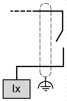
Fast input wiring for I0... I7:

The following figure shows the sink wiring (positive logic) of the controller digital inputs:

* Type T fuse
(1) The COM0, COM1 and COM2 terminals are not connected internally.
The following figure shows the source wiring (negative logic) of the controller digital inputs:

* Type T fuse
(1) The COM0, COM1 and COM2 terminals are not connected internally.
Fast input wiring for I0... I7:

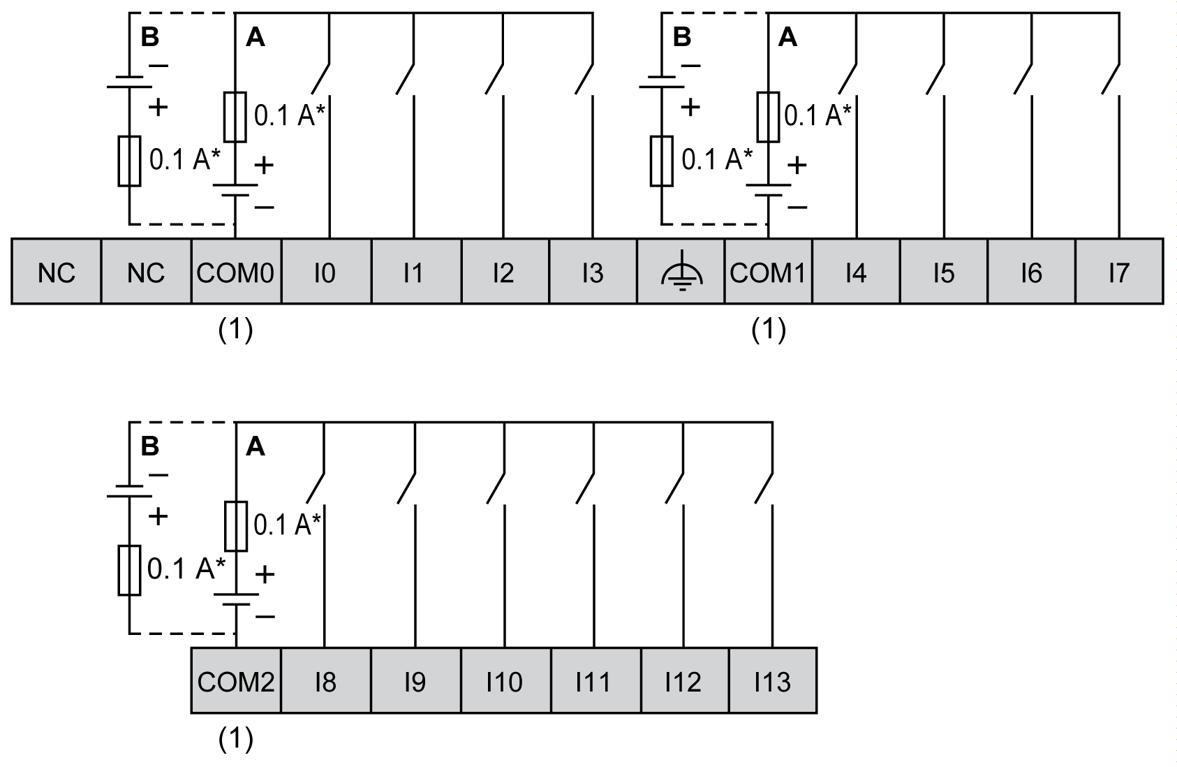
TM241C••24T / TM241C••24U Wiring Diagrams
The following figure shows the connection of the controller digital inputs:

* Type T fuse
(1) The COM0, COM1 and COM2 terminals are not connected internally.
A Sink wiring (positive logic).
B Source wiring (negative logic).
Fast input wiring for I0... I7:

|
|
|
UNINTENDED EQUIPMENT OPERATION |
|
Do not connect wires to unused terminals and/or terminals indicated as “No Connection (N.C.)”. |
|
Failure to follow these instructions can result in death, serious injury, or equipment damage. |
TM241C•40T / TM241C•40U Wiring Diagrams
The following figure shows the connection of the controller digital inputs:

* Type T fuse
(1) The COM0, COM1 and COM2 terminals are not connected internally.
A Sink wiring (positive logic).
B Source wiring (negative logic).
Fast input wiring for I0... I7:

|
|
|
UNINTENDED EQUIPMENT OPERATION |
|
Do not connect wires to unused terminals and/or terminals indicated as “No Connection (N.C.)”. |
|
Failure to follow these instructions can result in death, serious injury, or equipment damage. |