The Modicon M241 Logic Controller has digital outputs embedded:
|
Reference |
Total number of digital outputs |
|||
|---|---|---|---|---|
|
TM241C••24R |
10 |
4 |
6 |
0 |
|
TM241C••24T TM241C••24U |
10 |
4 |
0 |
6 |
|
TM241C•40R |
16 |
4 |
12 |
0 |
|
TM241C•40T TM241C•40U |
16 |
4 |
0 |
12 |
|
(1) Fast transistor outputs which can be used as 100 kHz PTO outputs |
||||
For more information, refer to Output Management.
|
|
|
FIRE HAZARD |
|
oUse only the correct wire sizes for the maximum current capacity of the I/O channels and power supplies. |
|
Failure to follow these instructions will result in death or serious injury. |
|
|
|
UNINTENDED EQUIPMENT OPERATION |
|
Do not exceed any of the rated values specified in the environmental and electrical characteristics tables. |
|
Failure to follow these instructions can result in death, serious injury, or equipment damage. |
Regular Transistor Outputs Status LEDs
The following figure shows the status LEDs for the TM241C••24• controller (the TM241C•40• controllers are similar with 40 LEDs):

|
LED |
Color |
Status |
Description |
|---|---|---|---|
|
0...9 |
Green |
On |
The output channel is activated |
|
Off |
The output channel is deactivated |
Regular Transistor Outputs Characteristics
The following table describes the characteristics of the M241 Logic Controller regular transistor outputs:
|
Characteristic |
TM241C••24T |
TM241C••24U |
TM241C•40T |
TM241C•40U |
|
|---|---|---|---|---|---|
|
Number of regular transistor outputs |
6 outputs (Q4...Q9) |
12 outputs (Q4...Q15) |
|||
|
Number of channel groups |
1 common line for Q4...Q7 common line for Q8, Q9 |
1 common line for Q4...Q7 common line for Q8...Q11 common line for Q12...Q15 |
|||
|
Output type |
Transistor |
||||
|
Logic type |
Source |
Sink |
Source |
Sink |
|
|
Rated output voltage |
24 Vdc |
||||
|
Output voltage range |
19.2...28.8 Vdc |
||||
|
Rated output current |
0.5 A |
||||
|
Total output current per group |
0.5A x number of outputs of the group |
||||
|
Voltage drop |
1 Vdc max |
||||
|
Leakage current when switched off |
< 5 µA |
||||
|
Maximum power of filament lamp |
2.4 W max |
||||
|
Derating |
No derating |
||||
|
Turn on time |
Max. 34 µs |
||||
|
Turn off time |
Max. 250 µs |
||||
|
Protection against short circuit |
Yes |
||||
|
Short circuit output peak current |
1.3 A |
||||
|
Automatic rearming after short circuit or overload |
Yes, every 10 ms |
||||
|
Clamping voltage |
Max. 39 Vdc +/- 1 Vdc |
||||
|
Maximum output frequency |
1 kHz |
||||
|
Isolation |
Between output and internal logic |
500 Vac |
|||
|
Between output terminals |
Not isolated |
||||
|
Connection type |
Removable screw terminal block |
||||
|
Connector insertion/removal durability |
Over 100 times |
||||
|
Cable |
Type |
Unshielded |
|||
|
Length |
Max 50 m (164 ft) |
||||
Refer to Removing Terminal Block.
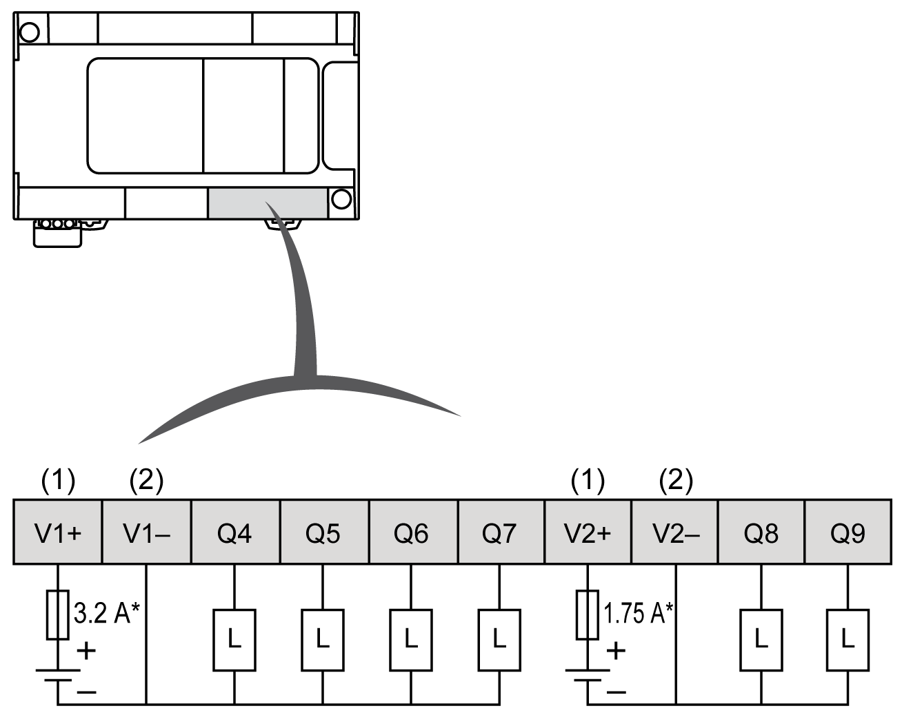
TM241C••24T Regular Transistor Outputs Source Wiring Diagram
The following figure shows the source wiring (positive logic) of the outputs:

* Type T fuse
(1) The V1+ and V2+ terminals are not connected internally.
(2) The V1– and V2– terminals are not connected internally.
|
|
|
UNINTENDED EQUIPMENT OPERATION |
|
Ensure that the physical wiring respects the connections indicated in the wiring diagram, and, in particular, that both V•+ and V•- are connected, and that only 24Vdc is connected to the V•+ terminal(s) and only 0Vdc is connected to the V•- terminal(s). |
|
Failure to follow these instructions can result in death, serious injury, or equipment damage. |
TM241C•40T Regular Transistor Outputs Source Wiring Diagram
The following figure shows the source wiring (positive logic) of the outputs:

* Type T fuse
(1) The V1+, V2+ and V3+ terminals are not connected internally.
(2) The V1–, V2– and V3– terminals are not connected internally.
|
|
|
UNINTENDED EQUIPMENT OPERATION |
|
Ensure that the physical wiring respects the connections indicated in the wiring diagram, and, in particular, that both V•+ and V•- are connected, and that only 24Vdc is connected to the V•+ terminal(s) and only 0Vdc is connected to the V•- terminal(s). |
|
Failure to follow these instructions can result in death, serious injury, or equipment damage. |
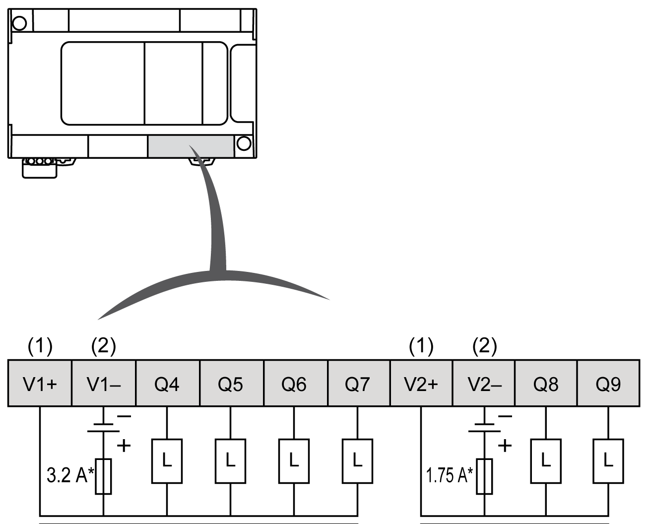
TM241C••24U Regular Transistor Outputs Sink Wiring Diagrams
The following figure shows the sink wiring (negative logic) of the outputs:

* Type T fuse
(1) The V1+ and V2+ terminals are not connected internally.
(2) The V1– and V2– terminals are not connected internally.
|
|
|
UNINTENDED EQUIPMENT OPERATION |
|
Ensure that the physical wiring respects the connections indicated in the wiring diagram, and, in particular, that both V•+ and V•- are connected, and that only 24Vdc is connected to the V•+ terminal(s) and only 0Vdc is connected to the V•- terminal(s). |
|
Failure to follow these instructions can result in death, serious injury, or equipment damage. |
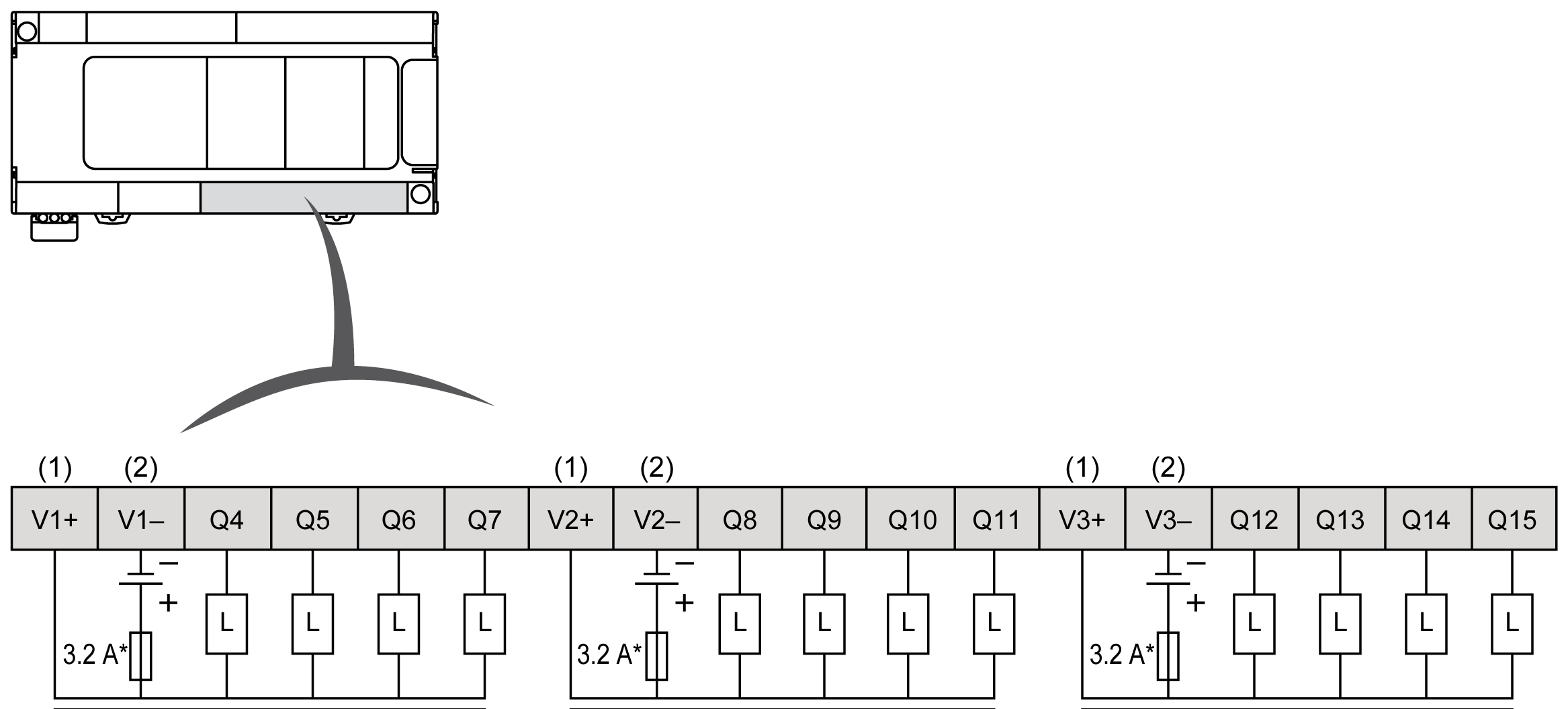
TM241C•40U Regular Transistor Outputs Sink Wiring Diagrams
The following figure shows the sink wiring (negative logic) of the outputs:

* Type T fuse
(1) The V1+, V2+ and V3+ terminals are not connected internally.
(2) The V1–, V2– and V3– terminals are not connected internally.
|
|
|
UNINTENDED EQUIPMENT OPERATION |
|
Ensure that the physical wiring respects the connections indicated in the wiring diagram, and, in particular, that both V•+ and V•- are connected, and that only 24Vdc is connected to the V•+ terminal(s) and only 0Vdc is connected to the V•- terminal(s). |
|
Failure to follow these instructions can result in death, serious injury, or equipment damage. |