The Modicon M241 Logic Controller CANopen master has the following features:
|
Feature |
Description |
|---|---|
|
Maximum number of slaves on the bus |
63 CANopen slave devices |
|
Maximum length of CANopen fieldbus cables |
According to the CAN specification (see Transmission Speed and Cable Length). |
|
Maximum number of PDOs managed by the master |
For each additional CANopen slave:
othe application size increases by an average of 10 kbytes, which conceivably could result in exceeding memory limits.
othe configuration initialization time at the startup increases, which conceivably could result in watchdog timeout.
Although EcoStruxure Machine Expert does not restrict you from doing so, do not exceed more than 63 CANopen slave modules (and/or 252 TPDOs and 252 RPDOs) in order to have a sufficient performance tolerance and avoid any performance degradation.
|
|
|
UNINTENDED EQUIPMENT OPERATION |
|
Do not connect more than 63 CANopen slave devices to the controller to avoid system overload watchdog condition. |
|
Failure to follow these instructions can result in death, serious injury, or equipment damage. |
|
NOTICE |
|
DEGRADATION OF PERFORMANCE |
|
Do not exceed more than 252 TPDOs and 252 RPDOs for the Modicon M241 Logic Controller. |
|
Failure to follow these instructions can result in equipment damage. |
The Modicon M241 Logic Controller J1939 master has the following features:
|
Feature |
Description |
|---|---|
|
Maximum number of ECUs (slaves) on the bus |
Limited only by the address range of 0...253 for Electronic Control Units (ECUs). |
|
Maximum length of J1939 fieldbus cables |
According to the CAN specification (see Transmission Speed and Cable Length). For J1939, the CAN bus must be configured to run at 250 Kbps. |
|
Maximum number of PGNs managed by the master |
Given implicitly by the maximum number of input bits (%I) and output bits (%Q) available on the Modicon M241 Logic Controller: 4096 input bits and 4096 output bits. This results in a maximum of 512 single-packet PGNs (most PGNs are single-packet, containing 8 bytes of data). |
For each additional ECU with approximately 10 configured (single frame) Parameter Group Numbers (PGNs):
othe application size increases by an average of 15 Kbytes. This figure includes the memory consumed by implicitly-generated variables for configured Suspected Parameter Numbers (SPNs). This application size increase could result in exceeding memory limits.
othe number of input bits (%I) used on the logic controller increases in proportion to the number and size of PGNs configured as "TX Signals" in a non-local ECU or "RX Signals" in a local ECU.
othe number of output bits (%Q) used on the logic controller increases in proportion to the number and size of PGNs configured as "TX Signals" in a local ECU.
NOTE: Thoroughly test your application regarding the number of configured J1939 ECUs connected to the controller, and the number of PGNs configured on each ECU, to avoid a system overload watchdog condition or performance degradation.
For more information, refer to J1939 Interface Configuration.
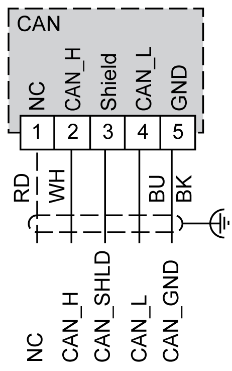
Refer to Removing Terminal Block.

|
Pin |
Signal |
Description |
Marking |
Color of Cable |
|---|---|---|---|---|
|
1 |
Not used |
Reserved |
NC |
RD: red |
|
2 |
CAN_H |
CAN_L bus line (dominant low) |
CAN_H |
WH: white |
|
3 |
CAN_SHLD |
Optional CAN shield |
Shield |
- |
|
4 |
CAN_L |
CAN_L bus line (dominant low) |
CAN_L |
BU: blue |
|
5 |
CAN_GND |
CAN Ground |
GND |
BK: black |
|
|
|
UNINTENDED EQUIPMENT OPERATION |
|
Do not connect wires to unused terminals and/or terminals indicated as “No Connection (N.C.)”. |
|
Failure to follow these instructions can result in death, serious injury, or equipment damage. |
Transmission Speed and Cable Length
Transmission speed is limited by the bus length and the type of cable used.
The following table describes the relationship between the maximum transmission speed and the bus length (on a single CAN segment without a repeater):
|
Maximum transmission baud rate |
Bus length |
|---|---|
|
1000 Kbps |
20 m (65 ft) |
|
800 Kbps |
40 m (131 ft) |
|
500 Kbps |
100 m (328 ft) |
|
250 Kbps |
250 m (820 ft) |
|
125 Kbps |
500 m (1,640 ft) |
|
50 Kbps |
1000 m (3280 ft) |
|
20 Kbps |
2500 m (16,400 ft) |
NOTE: The CAN cable must be shielded.