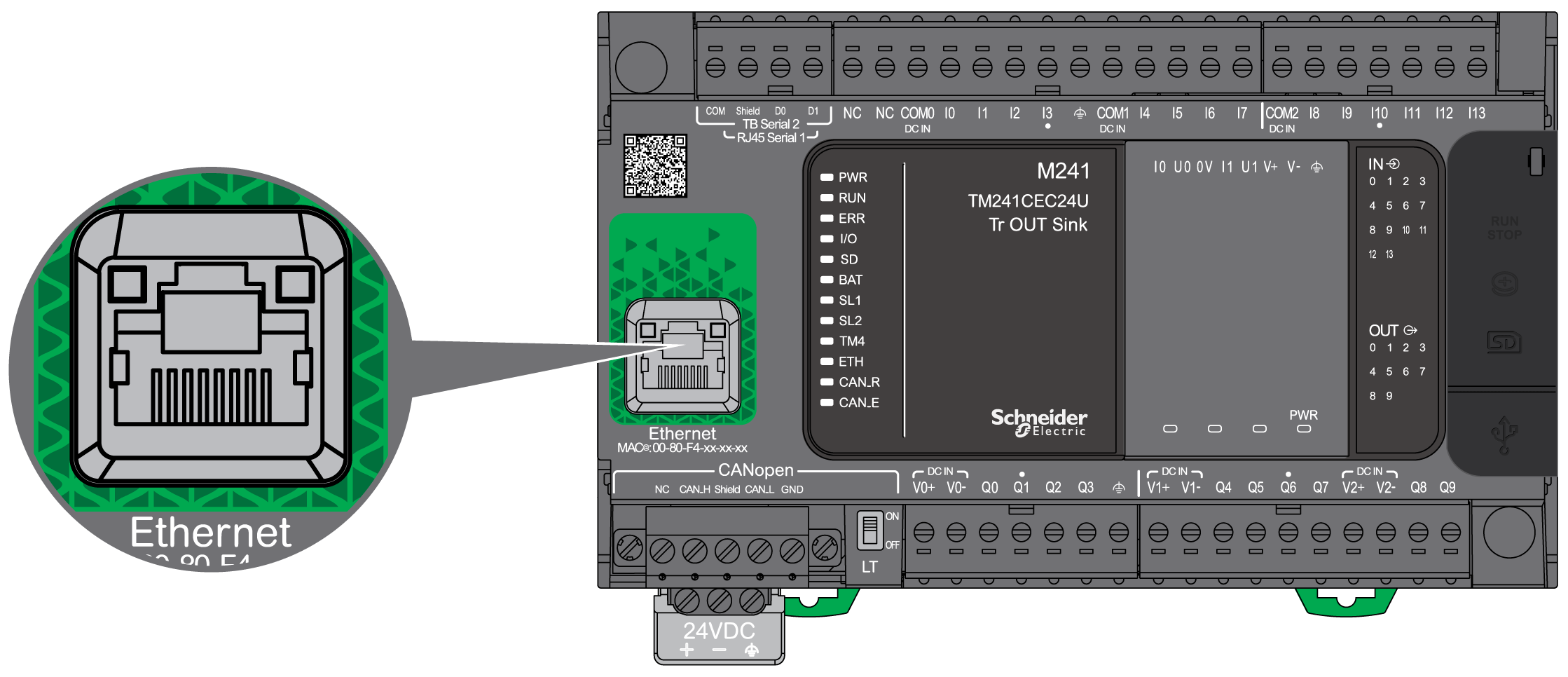
The TM241CE••• are equipped with an Ethernet communications port.
The following figure shows the location of the Ethernet port on the controller:

The following table describes the Ethernet characteristics:
|
Characteristic |
Description |
|---|---|
|
Function |
Modbus TCP/IP |
|
Connector type |
|
|
Auto negotiation |
from 10 M half duplex to 100 M full duplex |
|
Cable type |
Shielded |
|
Automatic cross-over detection |
Yes |
The following figure shows the RJ45 Ethernet connector pin assignment:

The following table describes the RJ45 Ethernet connector pins:
|
Pin N° |
Signal |
|---|---|
|
1 |
TD+ |
|
2 |
TD- |
|
3 |
RD+ |
|
4 |
- |
|
5 |
- |
|
6 |
RD- |
|
7 |
- |
|
8 |
- |
NOTE: The controller supports the MDI/MDIX auto-crossover cable function. It is not necessary to use special Ethernet crossover cables to connect devices directly to this port (connections without an Ethernet hub or switch).
NOTE: Ethernet cable disconnection is detected every second. In case of disconnection of a short duration (< 1 second), the network status may not indicate the disconnection.
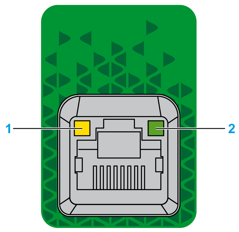
The following figure shows the RJ45 connector status LED:

The following table describes the Ethernet status LED:
|
Label |
Description |
LED |
||
|---|---|---|---|---|
|
Color |
Status |
Description |
||
|
1 |
Ethernet Link |
Green/Yellow |
Off |
No link |
|
Solid yellow |
Link at 10 Mbit/s |
|||
|
Solid green |
Activity at 100 Mbit/s |
|||
|
2 |
Ethernet Activity |
Green |
Off |
No activity |
|
On |
Transmitting or receiving data |
|||