M241 Logic Controller Mounting Positions and Clearances
This section describes the mounting positions for the M241 Logic Controller .
NOTE: Keep adequate spacing for proper ventilation and to maintain the operating temperature specified in the Environmental Characteristics.
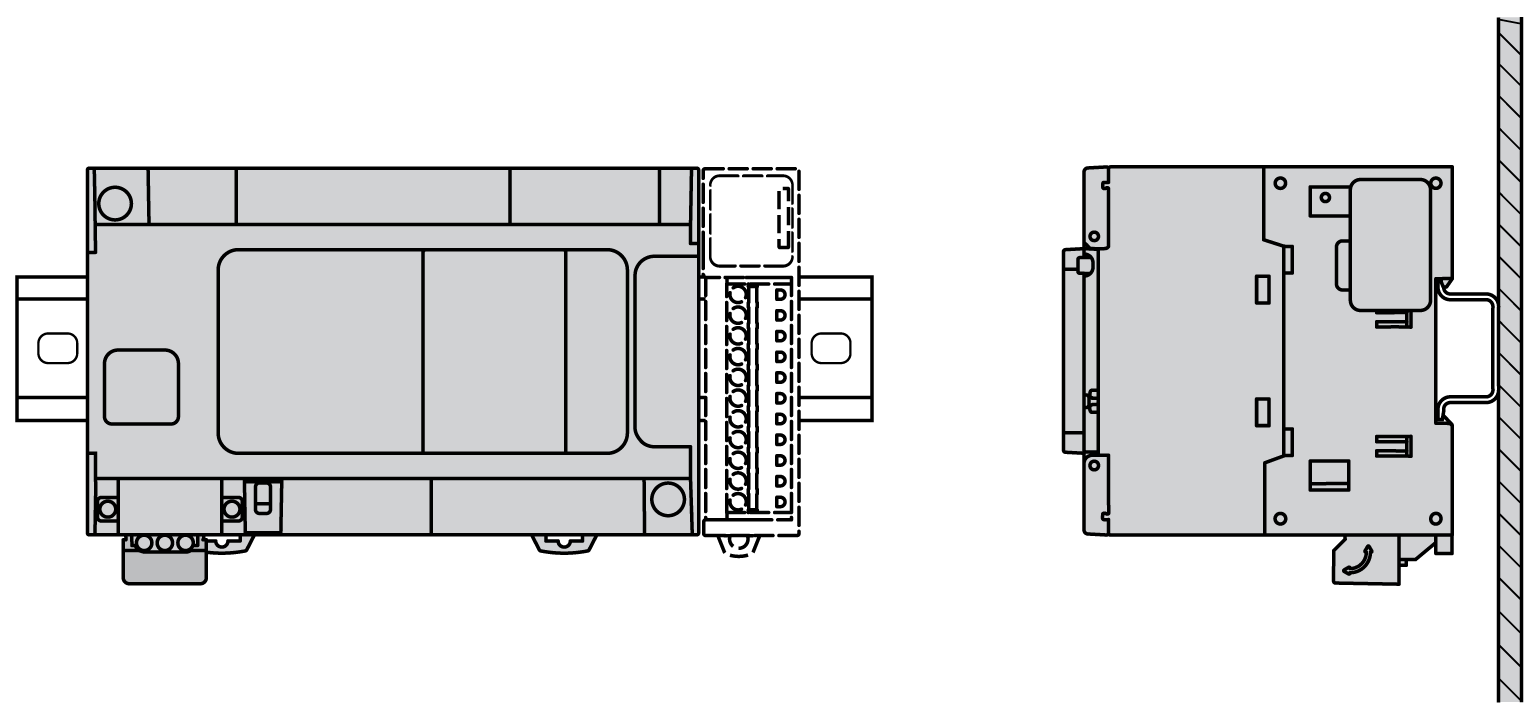
Whenever possible, the M241 Logic Controller should be mounted horizontally on a vertical plane as shown in the figure below:

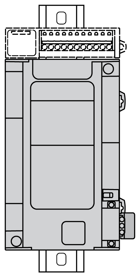
The M241 Logic Controller can also be mounted vertically with a temperature derating on a vertical plane as shown below.

NOTE: Expansion modules must be mounted above the logic controller.
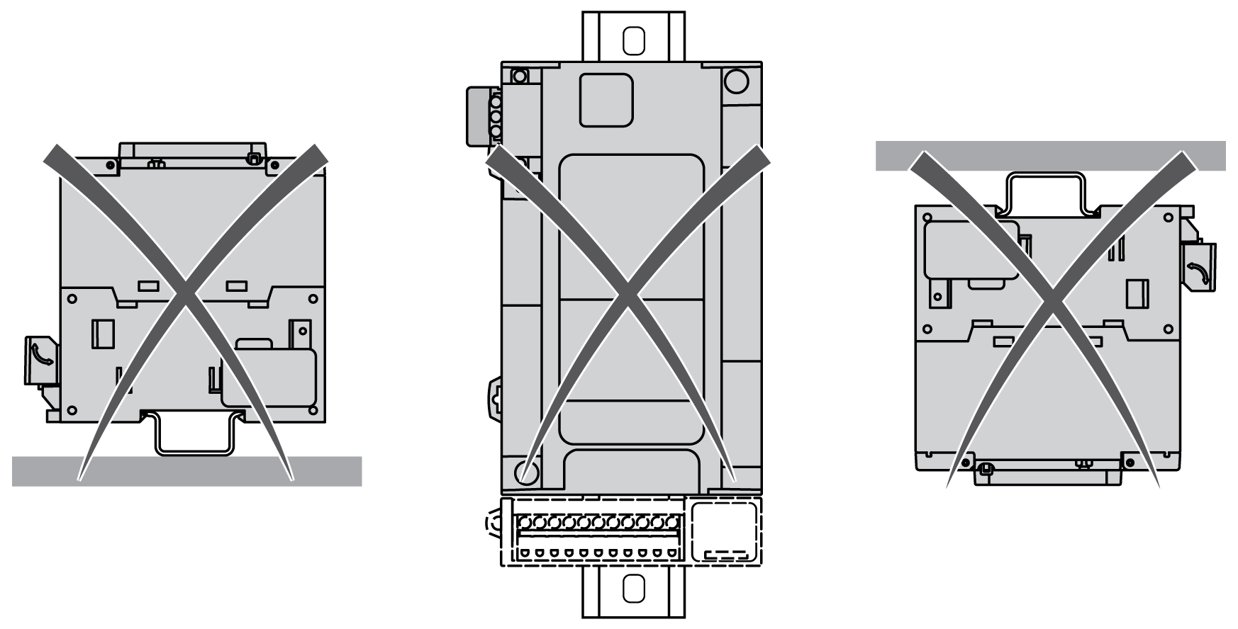
The M241 Logic Controller should only be positioned as shown in Correct Mounting Position figure. The figures below show the incorrect mounting positions.

|
|
|
UNINTENDED EQUIPMENT OPERATION |
|
oPlace devices dissipating the most heat at the top of the cabinet and ensure adequate ventilation. oAvoid placing this equipment next to or above devices that might cause overheating. oInstall the equipment in a location providing the minimum clearances from all adjacent structures and equipment as directed in this document. oInstall all equipment in accordance with the specifications in the related documentation. |
|
Failure to follow these instructions can result in death, serious injury, or equipment damage. |
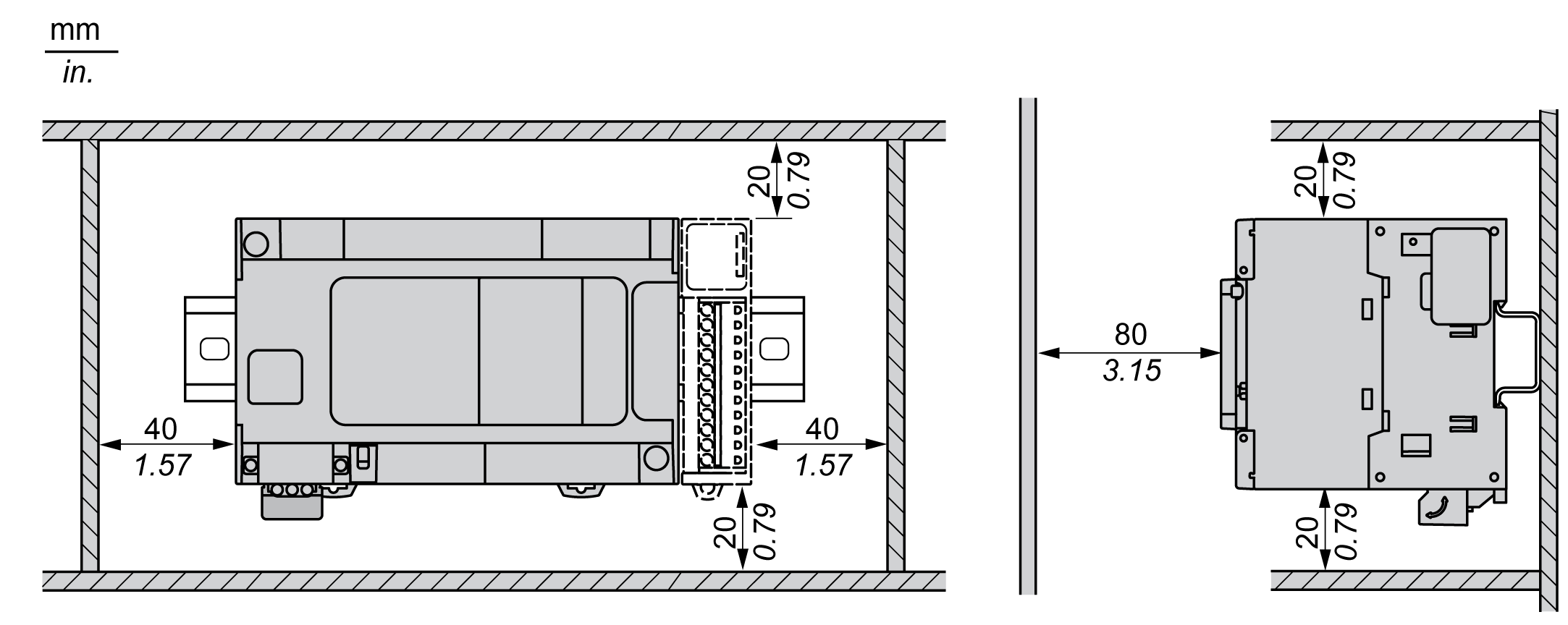
The M241 Logic Controller has been designed as an IP20 product and must be installed in an enclosure. Clearances must be respected when installing the product.
There are 3 types of clearances between:
oThe M241 Logic Controller and all sides of the cabinet (including the panel door).
oThe M241 Logic Controller terminal blocks and the wiring ducts. This distance reduces electromagnetic interference between the controller and the wiring ducts.
oThe M241 Logic Controller and other heat generating devices installed in the same cabinet.
The following figure shows the minimum clearances that apply to all M241 Logic Controller references:
