Four pulse width modulation functions can be configured on the controller.
Adding a Pulse Width Modulation Function
|
Step |
Action |
|---|---|
|
1 |
Double-click the Pulse Generators node of your controller in the Devices Tree. |
|
2 |
Double-click the Pulse generation function value and select PWM. Result: The PWM configuration parameters appear. |
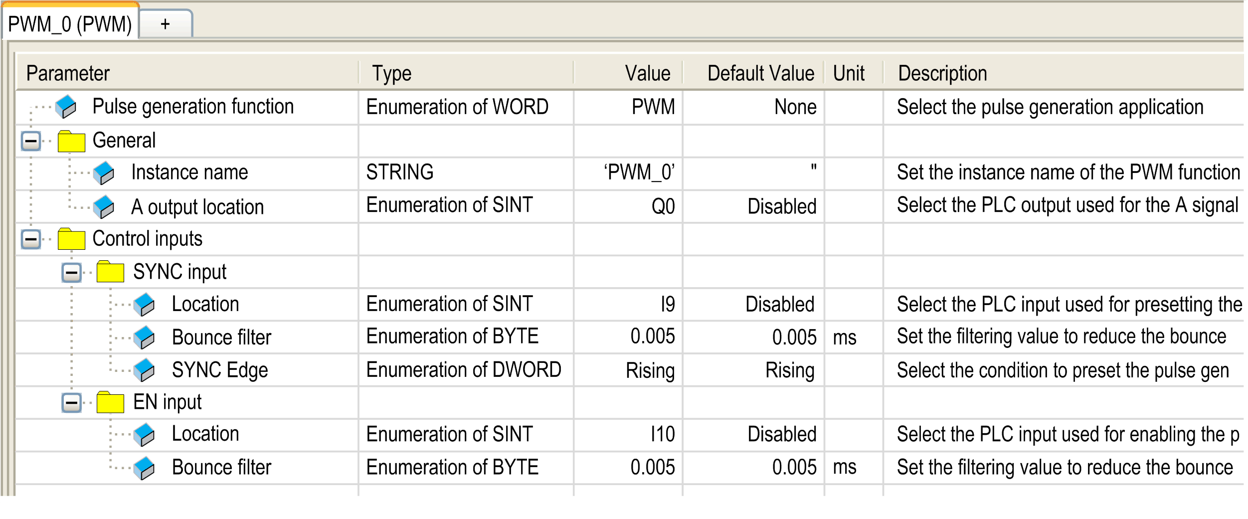
The figure provides an example of a PWM configuration window:

The pulse width modulation function has the following parameters:
|
Parameter |
Value |
Default |
Description |
|
|---|---|---|---|---|
|
General |
Instance name |
- |
PWM_0...PWM_3 |
Set the instance name of the PWM function. |
|
A output location |
Disabled Q0...Q3 (fast outputs) Q4...Q7 (regular outputs)(1) |
Disabled |
Select the controller output used for the A signal. |
|
|
Control inputs / SYNC input |
Location |
Disabled I0...I7 (fast inputs) I8...I13 (TM241•24• regular inputs) I8...I15 (TM241•40• regular inputs) |
Disabled |
Select the controller input used for presetting the PWM function. |
|
Bounce filter |
0.000 0.001 0.002 0.005 0.010 0.1 1.5 1 5 |
0.005 |
Set the filtering value to reduce the bounce effect on the SYNC input (in ms). |
|
|
SYNC Edge |
Rising Falling Both |
Rising |
Select the condition to preset the PWM function with the SYNC input. |
|
|
Control inputs / EN input |
Location |
Disabled I0...I7 (fast inputs) I8...I15 (TM241•40• regular inputs) I8...I13 (TM241•24• regular inputs) |
Disabled |
Select the controller input used for enabling the PWM function. |
|
Bounce filter |
0.000 0.001 0.002 0.005 0.010 0.1 1.5 1 5 |
0.005 |
Set the filtering value to reduce the bounce effect on the EN input (in ms). |
|
|
(1) Not available for M241 Logic Controller references with relay outputs. |
||||
Synchronizing with an External Event
On a rising edge on the IN_SYNC physical input (with EN_Sync = 1), the current cycle is interrupted and the PWM restarts a new cycle.
This illustration provides a pulse diagram for the Pulse Width Modulation function block with use of IN_SYNC input:
