The controller is the main element of the TM5 System.
The families of controllers are:
oModicon M258 Logic Controller
oModicon LMC058 Motion Controller
oModicon M241 Logic Controller in distributed architecture
oModicon M251 Logic Controller in distributed architecture
oModicon M262 Logic/Motion Controller in distributed architecture
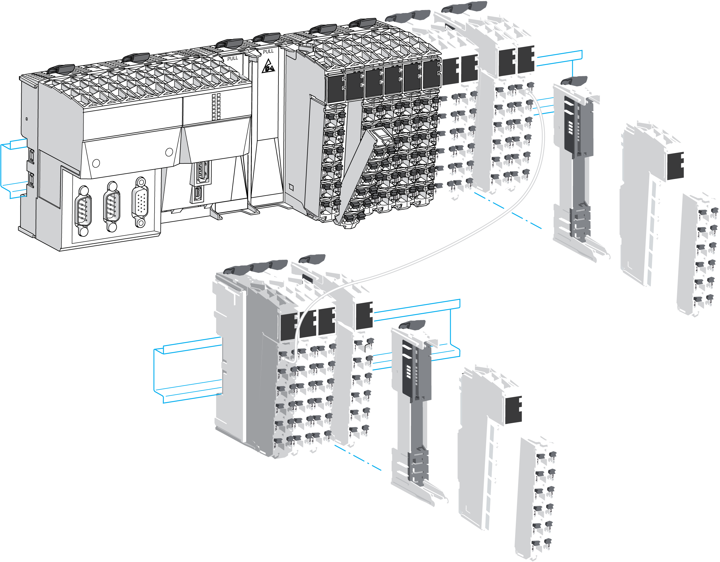
The following graphic depicts a typical TM5 System with the LMC058 motion controller:
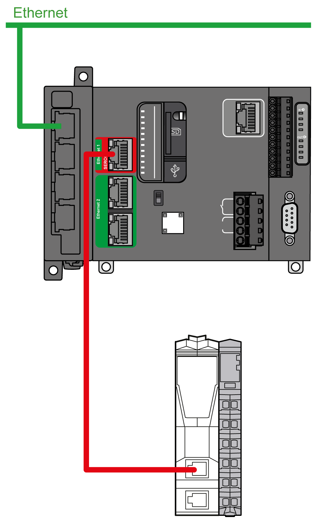
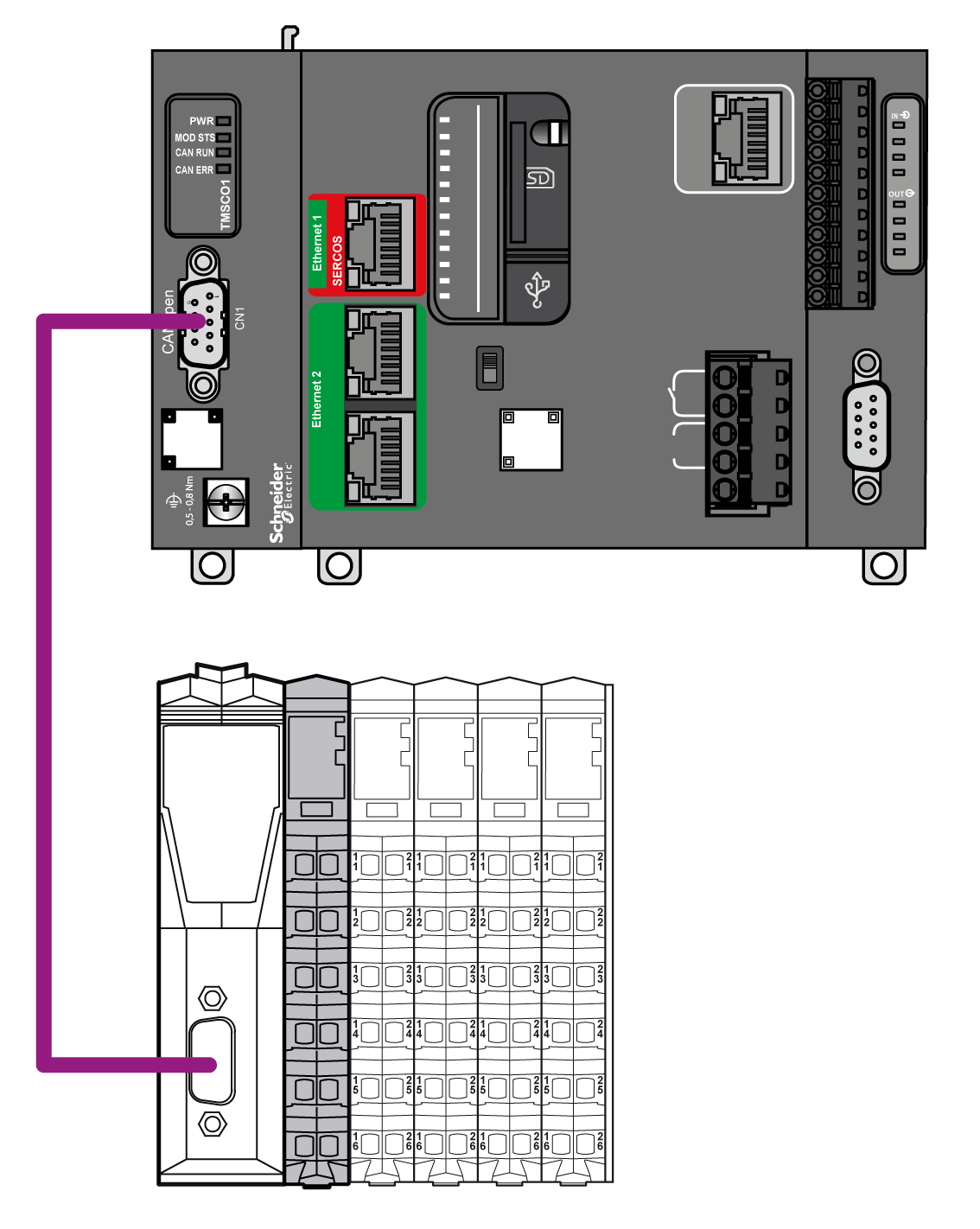
The following graphics represent distributed architectures using TM5 fieldbus interfaces:
|
|
Mechanical, hardware, and firmware features are described in the Modicon M258 Hardware Guide.
The following tables describes the controller references available for your TM5 System:
|
|
PCI |
CAN |
USB A |
USB Pgr |
Eth |
SL |
|---|---|---|---|---|---|---|
|
TM258LD42DT |
0 |
0 |
1 |
1 |
1 |
1 |
|
TM258LD42DT4L |
2 |
0 |
1 |
1 |
1 |
1 |
|
TM258LF42DT |
0 |
1 |
1 |
1 |
1 |
1 |
|
TM258LF42DT4L |
2 |
1 |
1 |
1 |
1 |
1 |
|
TM258LF66DT4L |
2 |
1 |
1 |
1 |
1 |
1 |
|
TM258LF42DR |
2 |
1 |
1 |
1 |
1 |
1 |
|
|
Embedded expert I/O |
Embedded regular I/O |
|||||||
|---|---|---|---|---|---|---|---|---|---|
|
|
Fast Inputs |
Fast Outputs |
Regular Inputs |
|
Digital Inputs |
Digital Outputs |
|
Analog Inputs |
|
|
TM258LD42DT |
2x |
5 |
2 |
2 |
1x |
12 |
12 |
0x |
0 |
|
TM258LD42DT4L |
2x |
5 |
2 |
2 |
1x |
12 |
12 |
1x |
4 |
|
TM258LF42DT |
2x |
5 |
2 |
2 |
1x |
12 |
12 |
0x |
0 |
|
TM258LF42DT4L |
2x |
5 |
2 |
2 |
1x |
12 |
12 |
1x |
4 |
|
TM258LF66DT4L |
2x |
5 |
2 |
2 |
2x |
12 |
12 |
1x |
4 |
|
TM258LF42DR |
2x |
5 |
2 |
2 |
2x |
6 |
6 Relays |
0x |
0 |
Modicon LMC058 Motion Controller
Mechanical, hardware, and firmware features are described in the Modicon LMC058 Hardware Guide.
The following tables describe the controller references available for your TM5 System:
|
|
PCI |
CAN |
USB A |
USB Pgr |
Eth |
SL |
ENC |
|---|---|---|---|---|---|---|---|
|
LMC058LF42 |
0 |
2 |
1 |
1 |
1 |
1 |
1 |
|
LMC058LF424 |
2 |
2 |
1 |
1 |
1 |
1 |
1 |
|
|
Embedded expert I/O |
Embedded regular I/O |
|||||||
|---|---|---|---|---|---|---|---|---|---|
|
|
Fast Inputs |
Fast Outputs |
Regular Inputs |
|
Digital Inputs |
Digital Outputs |
|
Analog Inputs |
|
|
LMC058LF42 |
2x |
5 |
2 |
2 |
1x |
12 |
12 |
0x |
0 |
|
LMC058LF424 |
2x |
5 |
2 |
2 |
1x |
12 |
12 |
1x |
4 |
M258 / LMC058 Controller Main Features
The following figure gives the main features of a controller:
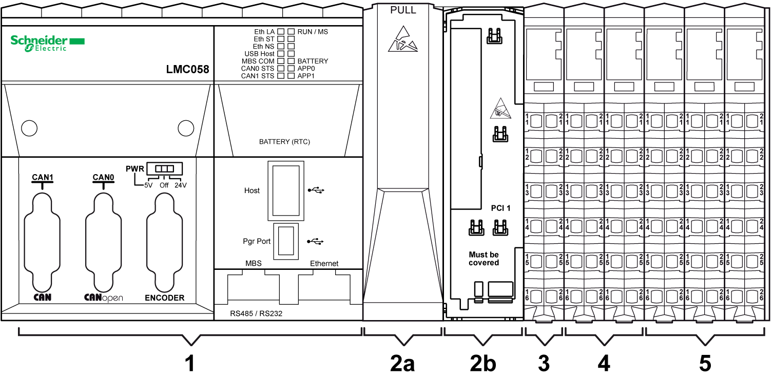
1 Controller
2a PCI slot with cover
2b PCI slot with cover removed
3 Controller Power Distribution Module (CPDM)
4 Embedded expert I/Os
5 Embedded regular I/Os
There are two PCI slots to connect up to two interface modules depending on the controller reference.
The following figure shows the location of PCI slots of the controllers:
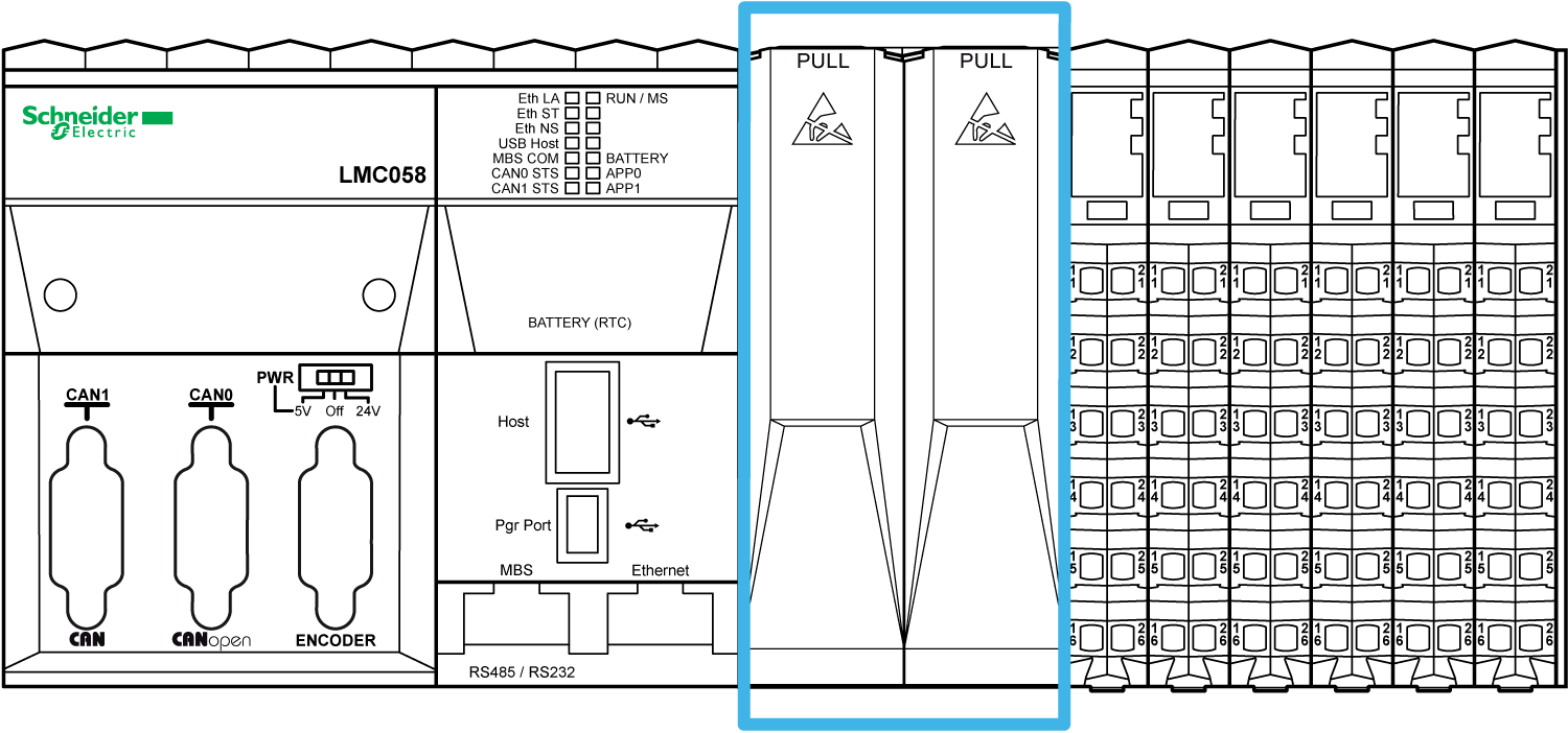
The PCI modules are used for specific application expansions of the controller. They are inserted in the PCI slots of the controller:
|
Reference |
Type |
Description |
|---|---|---|
|
TM5PCRS2 |
Serial line |
TM5 interface electronic module, 1 RS-232, electrically isolated |
|
TM5PCRS4 |
Serial line |
TM5 interface electronic module, 1 RS-485, electrically isolated |
|
TM5PCDPS |
TM5 interface electronic module, 1 RS-485, electrically isolated |
For more details refer to the Modicon TM5 PCI Modules Hardware Guide.
|
NOTICE |
|
ELECTROSTATIC DISCHARGE |
|
oVerify that empty PCI slots have their covers in place before applying power to the controller. oNever touch an exposed PCI connector. |
|
Failure to follow these instructions can result in equipment damage. |
Controller Power Distribution Module (CPDM)
The distribution of power by the CDPM consists of three dedicated electrical circuits:
|
Designation |
Description |
|---|---|
|
24 Vdc embedded expert modules power |
24 Vdc power that serves the embedded expert I/O modules of the controller and the encoder (depends on references) |
|
24 Vdc Main power |
24 Vdc power that serves the electronics of the controller and generates independent power for: oPCI communication modules (depends on references), oModbus connected devices, oUSB keys, oElectronics of the embedded regular I/O, oTM5 power bus that serves the expansion modules. |
|
24 Vdc I/O power segment |
The 24 Vdc power that serves: othe embedded regular I/O, othe sensors and actuators connected to the embedded regular I/O, othe expansion modules, othe sensors and actuators connected to the expansion modules, othe external devices connected to the Common Distribution Modules (CDM). |
The following figure shows the terminal block assignments of the CPDM:
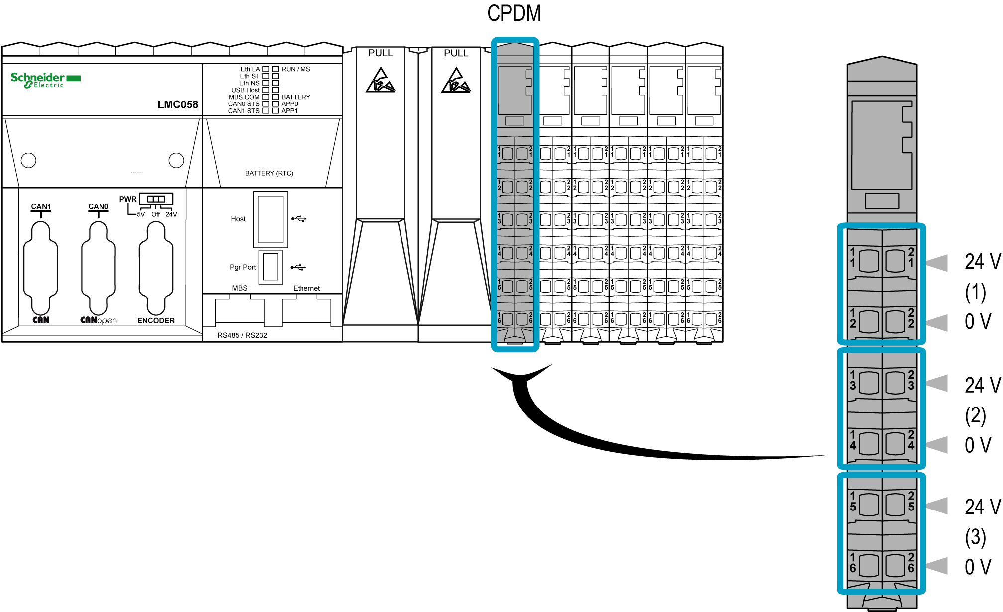
1 24 Vdc embedded expert modules power
2 24 Vdc Main power
3 24 Vdc I/O power segment
The following figure shows the location of the expert I/Os of the controller:
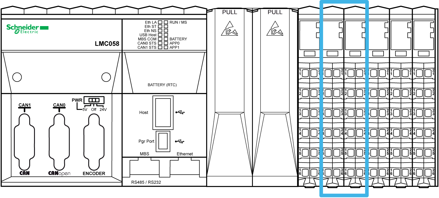
The controllers have two embedded expert I/O groups. Each group contains:
o5 fast inputs
o2 regular inputs
o2 fast outputs
Each group can be configured as:
o1 to 4 simple High Speed Counters (HSC)
o1 main HSC
o1 Pulse Width Modulated (PWM) output
o1 frequency generator
o1 encoder interface
Fast inputs resolution is up to 200 kHz.
NOTE: When a fast input is not used by special function, it can be used as a regular input.
Fast outputs resolution is up to 100 kHz.
NOTE: When a fast output is not used by special function, it can be used as a regular output.
The following figure shows the location of the embedded regular I/Os of the controller:
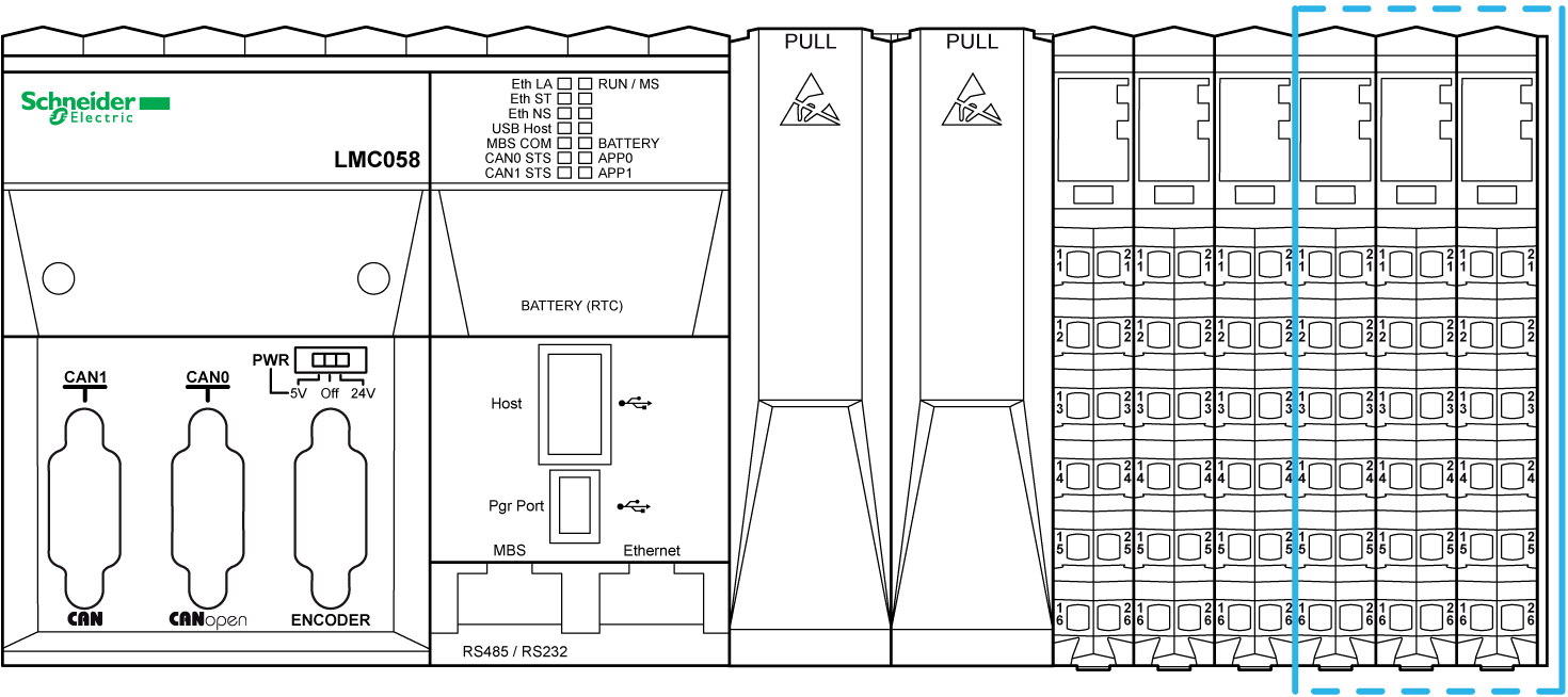
The following table gives a short description of the different regular I/Os embedded in the controller, depending on the controller reference:
|
Regular I/Os |
Short Description |
|---|---|
|
24 Vdc sink / 1 or 2 wires / input Type 1 |
|
|
24 Vdc source / 1 wire / transistor / 0.5 A |
|
|
12 bit resolution / -10...+10 Vdc / 0...20 mA / 4...20 mA |
|
|
Relay Outputs |
2 A / 30 Vdc / 240 Vac |
Mechanical, hardware, and firmware features are described in the Modicon M241 Logic Controller Hardware Guide.
|
Reference |
Digital Inputs |
Digital Outputs |
USB |
Eth |
SL |
CAN |
|---|---|---|---|---|---|---|
|
TM241C24R |
6 regular inputs(1) 8 fast inputs (counters)(2) |
6 2A relay outputs 4 source fast outputs (pulse generators)(3) |
1 |
– |
2 |
– |
|
TM241CE24R |
6 regular inputs(1) 8 fast inputs (counters)(2) |
6 2A relay outputs 4 source fast outputs (pulse generators)(3) |
1 |
1 |
2 |
– |
|
TM241CEC24R |
6 regular inputs(1) 8 fast inputs (counters)(2) |
6 2A relay outputs 4 source fast outputs (pulse generators)(3) |
1 |
1 |
2 |
1 |
|
TM241C24T |
6 regular inputs(1) 8 fast inputs (counters)(2) |
Source outputs 6 regular transistor outputs 4 fast outputs (pulse generators)(3) |
1 |
– |
2 |
– |
|
TM241CE24T |
6 regular inputs(1) 8 fast inputs (counters)(2) |
Source outputs 6 regular transistor outputs 4 fast outputs (pulse generators)(3) |
1 |
1 |
2 |
– |
|
TM241CEC24T |
6 regular inputs(1) 8 fast inputs (counters)(2) |
Source outputs 6 regular transistor outputs 4 fast outputs (pulse generators)(3) |
1 |
1 |
2 |
1 |
|
TM241C24U |
6 regular inputs(1) 8 fast inputs (counters)(2) |
Sink outputs 6 regular transistor outputs 4 fast outputs (pulse generators)(3) |
1 |
– |
2 |
– |
|
TM241CE24U |
6 regular inputs(1) 8 fast inputs (counters)(2) |
Sink outputs 6 regular transistor outputs 4 fast outputs (pulse generators)(3) |
1 |
1 |
2 |
– |
|
TM241CEC24U |
6 regular inputs(1) 8 fast inputs (counters)(2) |
Sink outputs 6 regular transistor outputs 4 fast outputs (pulse generators)(3) |
1 |
1 |
2 |
1 |
|
TM241C40R |
16 regular inputs(1) 8 fast inputs (counters)(2) |
12 2A relay outputs 4 source fast outputs (pulse generators)(3) |
1 |
– |
2 |
– |
|
TM241CE40R |
16 regular inputs(1) 8 fast inputs (counters)(2) |
12 2A relay outputs 4 source fast outputs (pulse generators)(3) |
1 |
1 |
2 |
– |
|
TM241C40T |
16 regular inputs(1) 8 fast inputs (counters)(2) |
Source outputs 12 regular transistor outputs 4 fast outputs (pulse generators)(3) |
1 |
– |
2 |
– |
|
TM241CE40T |
16 regular inputs(1) 8 fast inputs (counters)(2) |
Source outputs 12 regular transistor outputs 4 fast outputs (pulse generators)(3) |
1 |
1 |
2 |
– |
|
TM241C40U |
16 regular inputs(1) 8 fast inputs (counters)(2) |
Sink outputs 12 regular transistor outputs 4 fast outputs (pulse generators)(3) |
1 |
– |
2 |
– |
|
TM241CE40U |
16 regular inputs(1) 8 fast inputs (counters)(2) |
Sink outputs 12 regular transistor outputs 4 fast outputs (pulse generators)(3) |
1 |
1 |
2 |
– |
|
(1) The regular inputs have a maximum frequency of 1 kHz. (2) The fast inputs can be used either as regular inputs or as fast inputs for counting or event functions. (3) The fast transistor outputs can be used either as regular transistor outputs, as reflex outputs for counting function (HSC), or as fast transistor outputs for pulse generator functions (FreqGen / PTO / PWM). |
||||||
Mechanical, hardware, and firmware features are described in the Modicon M251 Logic Controller Hardware Guide.
|
Reference |
Digital Inputs |
Digital Outputs |
USB |
Eth |
SL |
CAN |
|---|---|---|---|---|---|---|
|
TM251MESC |
0 |
0 |
1 |
2 |
1 |
1 |
|
TM251MESE |
0 |
0 |
1 |
3(1) |
1 |
– |
|
(1) 1 duel port Ethernet switch + 1 Ethernet port for fieldbus |
||||||
Modicon M262 Logic/Motion Controller
Mechanical, hardware, and firmware features are described in the Modicon M262 Logic/Motion Controller Hardware Guide and Programming Guide.
The following table describes the available controller references:
|
Reference |
Fast Inputs |
Fast Outputs |
USB |
Eth |
SL |
ENC |
|---|---|---|---|---|---|---|
|
TM262L10MESE8T |
4 |
4 |
1 |
2(1) |
1 |
0 |
|
TM262L20MESE8T |
4 |
4 |
1 |
2(1) |
1 |
0 |
|
TM262M15MESS8T |
4 |
4 |
1 |
2(1)(2) |
1 |
1 |
|
TM262M25MESS8T |
4 |
4 |
1 |
2(1)(2) |
1 |
1 |
|
TM262M35MESS8T |
4 |
4 |
1 |
2(1)(2) |
1 |
1 |
|
(1) One dual port Ethernet switch, one Ethernet port for fieldbus. (2) One port can be used for Sercos Interface. NOTE: You can use the fast inputs/outputs as regular inputs/outputs. |
||||||