The following figure shows expansion bus cables used in TM5/TM7 configurations:

1 Attachment IN cable: to connect a TM7 I/O block after a TM5 configuration using a TM5SBET7 transmitter module.
2 Drop cable: to build TM7 expansion bus between TM7 expansions blocks.
3 Attachment OUT cable: to connect a TM5 remote island after a TM7 I/O block using a TM5SBER2 receiver module.
|
Length |
Short Description, Reference |
|||||
|---|---|---|---|---|---|---|
|
Drop Cable |
Attachment IN Cable |
Attachment OUT Cable |
||||
|
0.3 m (1 ft) |
TCSXCN2M2F03E |
TCSXCN1M1F03E |
– |
– |
– |
– |
|
1 m (3.3 ft) |
TCSXCN2M2F1E |
TCSXCN1M1F1E |
TCSXCN2FNX1E |
TCSXCN1FNX1E |
TCSXCN2MNX1E |
TCSXCN1MNX1E |
|
2 m (6.6 ft) |
TCSXCN2M2F2E |
TCSXCN1M1F2E |
– |
– |
– |
– |
|
3 m (9.8 ft) |
– |
– |
TCSXCN2FNX3E |
TCSXCN1FNX3E |
TCSXCN2MNX3E |
TCSXCN1MNX3E |
|
5 m (16.4 ft) |
TCSXCN2M2F5E |
TCSXCN1M1F5E |
– |
– |
– |
– |
|
10 m (32.8 ft) |
TCSXCN2M2F10E |
TCSXCN1M1F10E |
TCSXCN2FNX10E |
TCSXCN1FNX10E |
TCSXCN2MNX10E |
TCSXCN1MNX10E |
|
15 m (49.2 ft) |
TCSXCN2M2F15E |
TCSXCN1M1F15E |
– |
– |
– |
– |
|
25 m (82 ft) |
– |
– |
TCSXCN2FNX25E |
TCSXCN1FNX25E |
TCSXCN2MNX25E |
TCSXCN1MNX25E |
|
Dimensions and Pin Assignment |

|

|

|

|

|

|
The table below describes the characteristics of the individual wire pairs of the cable:
|
Wire |
Characteristics |
Value |
|---|---|---|
|
Power pair |
Conductor cross section (gauge) |
0.34 mm2 (AWG 22) |
|
Material insulation |
Polyolefin |
|
|
Core diameter including insulation |
1.40 mm (0.05 in.) ± 0.05 mm (0.002 in.) |
|
|
Electrical resistance (at 20 °C (68 °F)) |
≤ 0.052 Ω/m (0.016 Ω/ft) |
|
|
Insulation resistance (at 20 °C (68 °F)) |
≥ 100 ΜΩ*km (328 GΩ*ft) |
|
|
Nominal voltage |
300 V |
|
|
Test voltage conductor |
2000 Vdc x 1 s |
|
|
Data pair |
Conductor cross section (gauge) |
0.2 mm2 (AWG 24) |
|
Material insulation |
Foam-skin PE |
|
|
Core diameter including insulation |
2.05 mm (0.08 in.) ± 0.1 mm (0.004 in.) |
|
|
Electrical resistance (at 20 °C (68 °F)) |
≤ 0.078 Ω/m (0.024 Ω/ft) |
|
|
Insulation resistance (at 20 °C (68 °F)) |
≥ 5000 ΜΩ*km (16.4 TΩ*ft) |
|
|
Characteristic impedance (at 5 MHz) |
120 Ω |
|
|
Nominal voltage |
30 V |
|
|
Test voltage conductor |
1500 Vdc x 1 s |
The table below describes the general characteristics of the cable:
|
Characteristics |
Specification |
|
|---|---|---|
|
Cable type |
Special PUR black shielded |
|
|
Conductor material |
Stranded tinned copper |
|
|
Shield |
Tinned copper foil and drain wire |
|
|
External cable diameter |
6.7 mm (0.26 in.) ± 0.3 mm (0.012 in.) |
|
|
Minimum curve radius |
67 mm (2.63 in.) |
|
|
Maximum pulling strength |
Static application |
50 N/mm2 (7252 lbf/in2) |
|
Dynamic application |
20 N/mm2 (2901 lbf/in2) |
|
|
Wire colors |
Power pair |
Red, black |
|
Data pair |
Blue, white |
|
|
External sheath, color |
Black-gray RAL 7021 |
|
|
Cable weight |
54.8 kg/km (0.037 lb/ft) |
|
|
Number of bending cycles |
4 million |
|
|
Traversing path |
10 m (32.8 ft) |
|
|
Traversing rate |
3 m/s (9.8 ft/s) |
|
|
Acceleration |
10 m/s2 (32.8 ft/s2) |
|
|
M12 fastening torque |
Maximum 0.4 Nm (3.5 lbf-in) |
|
The table below describes the environmental characteristics of the cable:
|
Characteristics |
Specification |
|---|---|
|
Operating temperature |
–20...75 °C (–4...167 °F) |
|
Storage temperature |
–40...80 °C (–40...176 °F) |
|
Special properties |
Flexible cable conduit capable |
|
Silicone-free |
|
|
Freedom from halogen |
As per DIN VDE 0472 part 815 |
|
WEEE/RoHS |
Compliant |
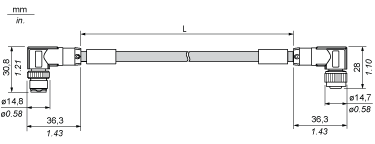
TCSXCN2M2F••E Dimensions and Pin Assignment
|
Dimensions |
||||
|---|---|---|---|---|
|
||||
|
L length as a function of the particular reference |
|
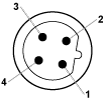
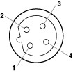
Pin Assignment |
||||
|---|---|---|---|---|
|
Male Connector |
Pin |
Designation |
Wire Color |
Female Connector |
|
1 |
TM7 V+ |
Red |
|
|
2 |
TM7 Bus Data |
White |
||
|
3 |
TM7 OV |
Black |
||
|
4 |
TM7 Bus Data |
Blue |
||
|
M12(1) |
SHLD |
Shield |
||
|
(1) Shielding 360 ° around M12 knurled screw. |
||||
TCSXCN1M1F••E Dimensions and Pin Assignment
|
Dimensions |
||||
|---|---|---|---|---|

|
||||
|
(L) length as a function of the particular reference |
|
Pin Assignment |
||||
|---|---|---|---|---|
|
Male Connector |
Pin |
Designation |
Wire Color |
Female Connector |

|
1 |
TM7 V+ |
Red |

|
|
2 |
TM7 Bus Data |
White |
||
|
3 |
TM7 OV |
Black |
||
|
4 |
TM7 Bus Data |
Blue |
||
|
M12(1) |
SHLD |
Shield |
||
|
(1) Shielding 360 ° around M12 knurled screw. |
||||
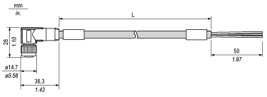
TCSXCN2FNX••E Dimensions and Pin Assignment
|
Dimensions |
||||
|---|---|---|---|---|
|
||||
|
(L) length as a function of the particular reference |
|
Pin Assignment |
||||
|---|---|---|---|---|
|
Female Connector |
Pin |
Designation |
Wire Color |
Open |

|
1 |
TM7 V+ |
Red |
For custom wiring |
|
2 |
TM7 Bus Data |
White |
||
|
3 |
TM7 OV |
Black |
||
|
4 |
TM7 Bus Data |
Blue |
||
|
M12(1) |
SHLD |
Shield |
||
|
(1) Shielding 360 ° around M12 knurled screw. |
||||
TCSXCN1FNX••E Dimensions and Pin Assignment
|
Dimensions |
||||
|---|---|---|---|---|

|
||||
|
(L) length as a function of the particular reference |
|
Pin Assignment |
||||
|---|---|---|---|---|
|
Female Connector |
Pin |
Designation |
Wire Color |
Open |

|
1 |
TM7 V+ |
Red |
For custom wiring |
|
2 |
TM7 Bus Data |
White |
||
|
3 |
TM7 OV |
Black |
||
|
4 |
TM7 Bus Data |
Blue |
||
|
M12(1) |
SHLD |
Shield |
||
|
(1) Shielding 360 ° around M12 knurled screw. |
||||
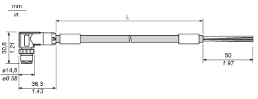
TCSXCN2MNX••E Dimensions and Pin Assignment
|
Dimensions |
||||
|---|---|---|---|---|
|
||||
|
(L) length as a function of the particular reference |
|
Pin Assignment |
||||
|---|---|---|---|---|
|
Male Connector |
Pin |
Designation |
Wire Color |
Open |

|
1 |
TM7 V+ |
Red |
For custom wiring |
|
2 |
TM7 Bus Data |
White |
||
|
3 |
TM7 OV |
Black |
||
|
4 |
TM7 Bus Data |
Blue |
||
|
M12(1) |
SHLD |
Shield |
||
|
(1) Shielding 360 ° around M12 knurled screw. |
||||
TCSXCN1MNX••E Dimensions and Pin Assignment
|
Dimensions |
||||
|---|---|---|---|---|

|
||||
|
(L) length as a function of the particular reference |
|
Pin Assignment |
||||
|---|---|---|---|---|
|
Male Connector |
Pin |
Designation |
Wire Color |
Open |

|
1 |
TM7 V+ |
Red |
For custom wiring |
|
2 |
TM7 Bus Data |
White |
||
|
3 |
TM7 OV |
Black |
||
|
4 |
TM7 Bus Data |
Blue |
||
|
M12(1) |
SHLD |
Shield |
||
|
(1) Shielding 360 ° around M12 knurled screw. |
||||