Maximum Hardware Configuration
The M262 Logic/Motion Controller is a control system that offers an all-in-one solution for motion applications and a scalable solution for logic applications, with optimized configurations and an open, expandable architecture.
Local and Remote Configuration Principle
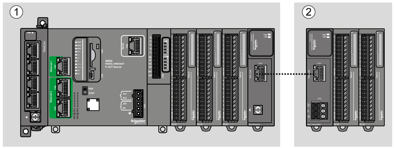
The following figure defines the local and remote configurations:

(1) Local configuration
(2) Remote configuration
M262 Logic/Motion Controller Local Configuration Architecture
Optimized local configuration and flexibility are provided by the association of:
oM262 Logic/Motion Controller
oTMS expansion modules
oTM3 expansion modules
Application requirements determine the architecture of your M262 Logic/Motion Controller configuration.
The following figure represents the components of a local configuration:

(A) TMS expansion modules (2 maximum: 1 TMSES4 and 1 TMSCO1).
TMSCO1 must always be the first module on the left.
(B) TM3 expansion modules (7 maximum).
M262 Logic/Motion Controller Remote Configuration Architecture
Optimized remote configuration and flexibility are provided by the association of:
oM262 Logic/Motion Controller
oTMS expansion modules
oTM3 expansion modules
oTM3 transmitter and receiver modules
Application requirements determine the architecture of your M262 Logic/Motion Controller configuration.
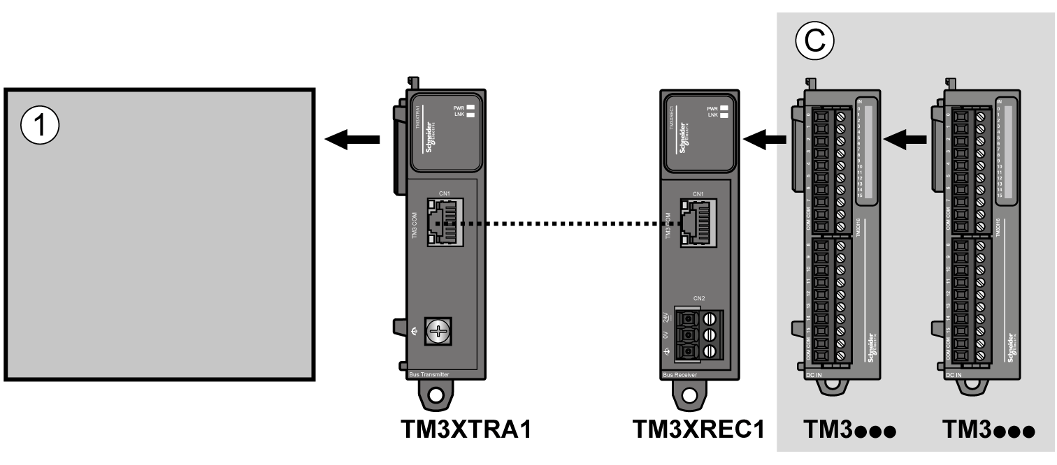
The following figure represents the components of a remote configuration:

(1) Logic/motion controller and modules
(C) TM3 expansion modules (7 maximum)
M262 Logic/Motion Controller Distributed Configuration Architecture
Optimized remote configuration and flexibility are provided by the association of:
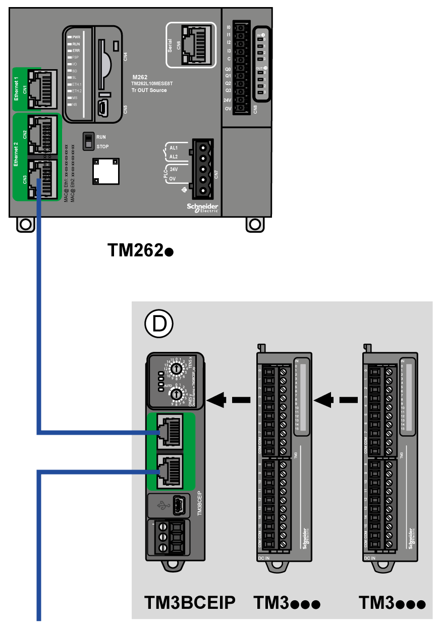
This figure shows the components of a distributed architecture:

(D) TM3 distributed modules
The following table shows the maximum configuration supported:
|
References |
Maximum |
Type of Configuration |
|
|---|---|---|---|
|
TM262• |
7 TM3 expansion modules |
Local |
|
|
2 TMS expansion modules |
Local |
||
|
TM3XREC1 |
7 TM3 expansion modules |
Remote |
|
|
TM3BCEIP |
7 TM3 expansion modules |
Distributed |
|
|
NOTE: TM3 transmitter and receiver modules are not included in a count of the maximum number of expansion modules. |
|||
NOTE: The configuration with its TMS and TM3 expansion modules is validated by EcoStruxure Machine Expert software in the Configuration window.
NOTE: In some environments, the maximum configuration populated by high power consumption modules, coupled with the maximum distance allowable between the TM3 transmitter and receiver modules, may present bus communication issues although the EcoStruxure Machine Expert software allowed for the configuration. In such a case you will need to analyze the power consumption of the modules chosen for your configuration, as well as the minimum cable distance required by your application, and possibly seek to optimize your choices.