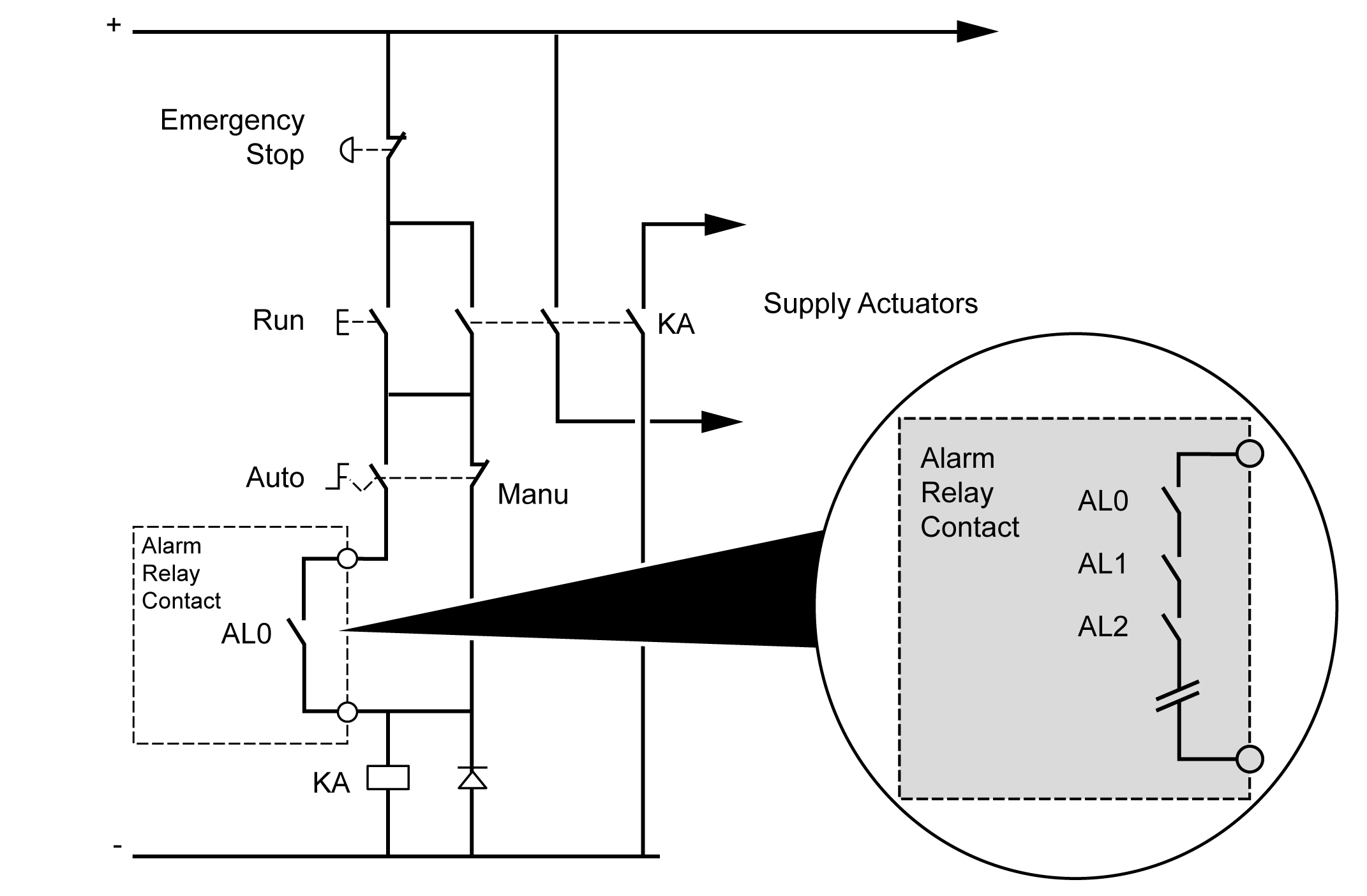
The M262 Logic/Motion Controller has integrated relay connections that can be wired to an external alarm.
Wiring Stripping and Wire Sizes
The alarm relay is wired by means of a 5.08 mm pitch removable screw terminal block on the front face of the M262 Logic/Motion Controller. For details, refer to Rules for Terminal Blocks.
Using the Alarm Relay for the Actuator Power Supply
|
Step |
Action |
|---|---|
|
1 |
Switch on the power supply of the M262 Logic/Motion Controller using the main contactor. |
|
2 |
When the M262 Logic/Motion Controller is powered on (PLC - Sensor), switch on the output power supply for the actuators using the KA contact. The following wiring diagram shows an M262 Logic/Motion Controller supplied by direct current: 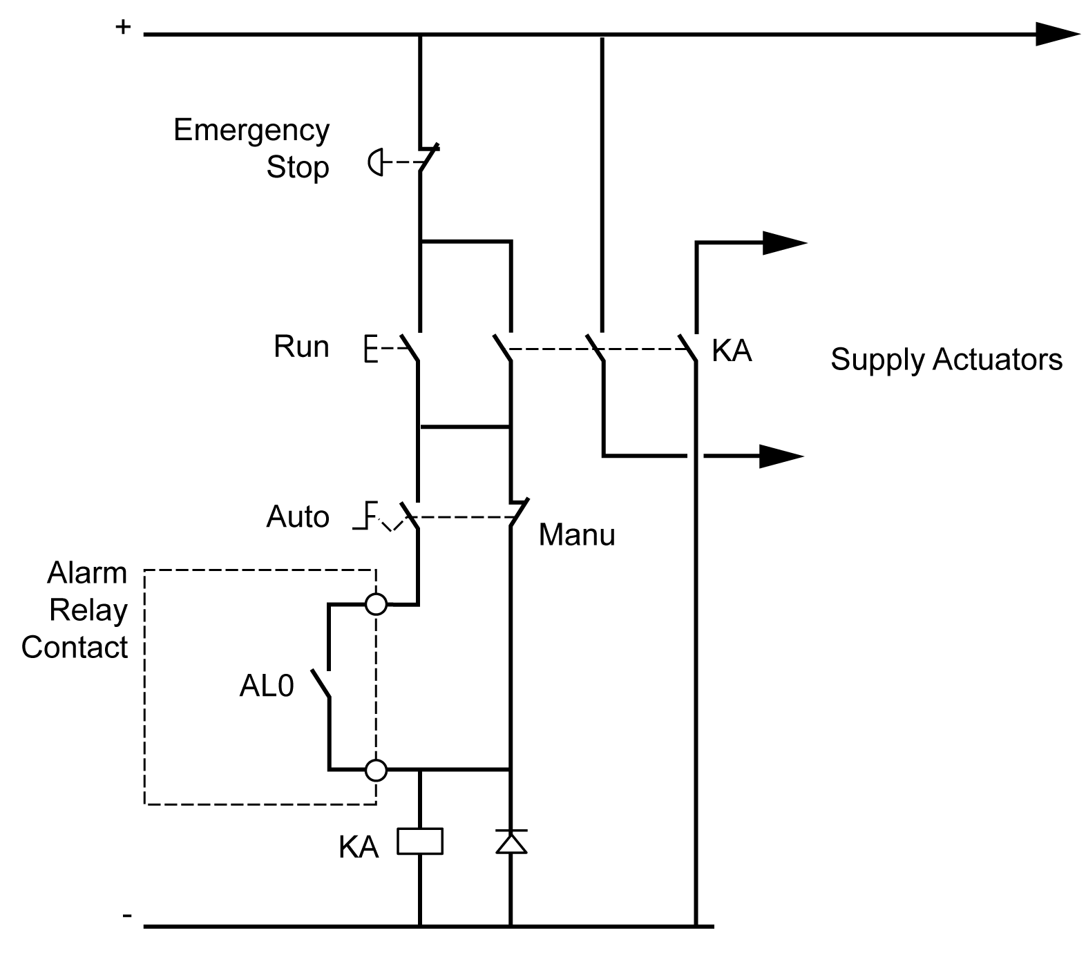
In AUTO run mode, the KA contact is controlled by the alarm relay from the power supply module. |
If your system comprises multiple M262 Logic/Motion Controllers installed in multiple racks, set the alarm relay contacts in all controllers in series (AL0, AL1, AL2, and so on), as shown in the following diagram: