This topic contains the following information
NOTE:
Term definition: The 'Devices' window is also referred to as Bus Navigator.
The Device Parameterization editor is part of the Bus Navigator. The editor is used to parameterize the safety-related devices contained in the bus project. These parameters are read from the device description file which is provided by each device. The file determines the device functionality during runtime.
For example, the parameters are used to specify module settings relating to the safety response time, signal evaluation, input filters settings, pulse mode, timebase, or units.
When compiling the project in EcoStruxure Machine Expert - Safety, a binary parameterization file is generated based on these parameters. This file is transmitted to the Safety Logic Controller when downloading the project. The Safety Logic Controller then transmits the parameter sets to the individual safety-related devices.
The Device Parameterization editor is located on the right of the devices tree in the 'Devices' window. Which parameters are available on which tabs depends on the device that is selected in the device tree.
NOTE:
Parameters can only be edited if you have logged-on at the appropriate level using the correct project password ('Project > Project Log On' menu item).
Device synchronization with the safety-related project
Each time when opening an existing project in EcoStruxure Machine Expert - Safety (by launching EcoStruxure Machine Expert - Safety in EcoStruxure Machine Expert), the list of safety-related devices in the bus project is synchronized with the device list contained in the safety-related project. This device synchronization is repeated cyclically as long as the project remains open in EcoStruxure Machine Expert - Safety.
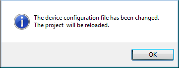
In case that devices have been added, deleted, or modified in the EcoStruxure Machine Expert 'Devices' tree, these modifications are automatically detected by the synchronization mechanism. First, the message dialog shown below appears. Click 'OK' to confirm the new bus structure and to reload the list of safety-related devices from EcoStruxure Machine Expert.

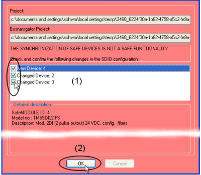
Then, the 'Confirm changed SDIO Devices' dialog appears. Here, each modification must be (1) confirmed separately by marking the appropriate checkbox to be able to open the safety-related project before (2) confirming the dialog with 'OK' as shown in the figure below.
The following figure shows an example:

WARNING
UNINTENDED EQUIPMENT OPERATION
Whenever you add, delete, or exchange devices in the bus structure, validate the physical wiring of your safety-related architecture and thoroughly test the application.
Failure to follow these instructions can result in death, serious injury, or equipment damage.
This way, the safety-related project is updated accordingly. When applying modifications in the bus configuration to the safety-related project, each modification is entered in the project log file and can be traced afterwards.
If you reject the modifications in the device list, EcoStruxure Machine Expert - Safety is closed (for example because a device has been deleted or added unintentionally).
NOTE:
Device synchronization is only possible if you are logged-on at 'Development' level using the correct project password.
Structure of the Device Parameterization editor
The editor is grid based. Above the first grid line, the editor shows the device type (reference, description) and the 'SafeModuleID' which represents the unique safety identifier of the safety-related device. Each safety-related device can be clearly identified via this ID. The 'SafeModuleID' was automatically assigned when configuring the bus structure in the 'Devices' tree in EcoStruxure Machine Expert. The synchronization of the safety-related device list is based on this information.
The fourth line on this tab shows the name of the import file in case you have imported parameters (see section "Importing/exporting safety-related device parameters").
The available parameters are then listed line by line. Depending on the device you are editing, the parameters may be summarized in groups. Each parameter (one grid line) consists of a read-only parameter name and an editable value. Refer to the next section.
NOTE:
Modifying safety-related device parameters is only possible if you are logged-on at 'Development' or 'Commissioning' level using the correct project password.
Commissioners can only modify parameters which are explicitly defined as commissioning parameters.
'Maintenance' users have read-only access to these parameters.
Each modification done in the parameterization is entered in the project log file and can be traced afterwards.
The device parameterization editor provides multiple Undo (<Ctrl> + <Z>) and Redo (<Ctrl> + <Y>) as long as the editor is not closed and no other device is selected.
Further Information
For detailed information about the meaning of the available parameters and values, refer to the hardware documentation of the device to be parameterized.
NOTE:
After editing a device parameter and saving the parameter grid by pressing the 'Save' icon, the project is marked as modified. A '*' symbol is added to the elements in the node project tree. The '*' is deleted after compiling the project.
Relevant Schneider Electric module parameter descriptions
Parameters of the available safety-related Schneider Electric modules are listed and described in the help chapter "Hardware Module Parameters".
Parameters that are relevant for the safety response time are additionally summarized and listed in the topic "Parameters for the Safety Response Time".
Exporting and importing safety-related device parameters
Once you have parameterized a safety-related device, you can export the parameter list into a file for later reuse.
How to export all parameters or a parameter group
To export the entire parameter list, right-click anywhere into the grid editor and select the context menu item 'Export...'.
To export one specific parameter group, right-click on the gray group name and select the context menu item 'Export group...'.
In both cases the export dialog appears.
The file extension for entire parameter files is *.spd, exported groups are stored in *.spg files.
Browse for a target directory, enter a file name, and click 'Save'.
How to import all parameters or a parameter group
To import an entire parameter list, right-click anywhere into the grid editor and select the context menu item 'Import...'.
To import one specific parameter group, right-click on any gray group name and select the context menu item 'Import group...'.
In both cases the import dialog appears.
Browse for the desired parameter file. The file extension for entire parameter files is *.spd, exported groups are stored in *.spg files. There are only these files displayed which are suitable for the present device.
After importing the parameter list, the parameters of the device are locked.
Select 'Unlock' from the context menu to edit parameters.
The name of the imported file is visible in the editor header (below the location ID). The import file name is removed again as soon as you modify any parameter for the present device.
Printing safety-related device parameters
The print dialog (menu item 'File > Print Project...') provides a checkbox 'Safety Parameters'. Marking this checkbox includes the safety-relevant device parameters in the printout.