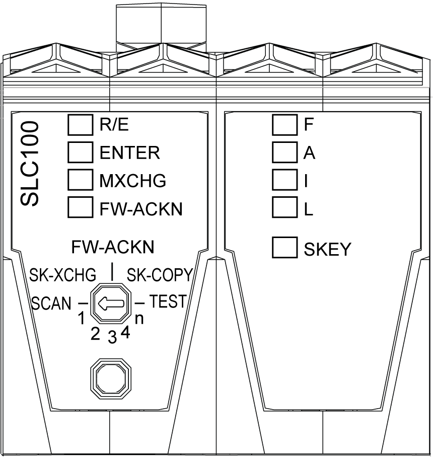
Logic Processor LED Indicators
Description of the LED Indicators for the Logic Processor
The figure and table present the LED indicators for the logic processor of the TM5CSLC100FS and TM5CSLC200FS:

|
LED indicator |
LED color |
LED status |
Description |
Instructions / information for the user |
|||
|---|---|---|---|---|---|---|---|
|
R/E |
N/A |
off |
Boot phase |
- |
|||
|
green |
on |
Application found and executed |
|||||
|
flashing |
Application exists but is not being processed |
||||||
|
orange |
on |
EcoStruxure Machine Expert - Safety software is in RUN (Debug) state |
|||||
|
flashing |
EcoStruxure Machine Expert - Safety software is in STOP (Debug) state or HALT (Debug) state, application stopped |
||||||
|
fast flashing |
No application found on the memory key |
||||||
|
ENTER(1) |
green |
on |
Waiting for confirmation |
- |
|||
|
1x flash every 0.8 s |
Confirmation of correct entry |
||||||
|
flashes (1 Hz) for 5 s |
Operator error detected |
||||||
|
MXCHG(1) |
orange |
off |
Valid module configuration |
- |
|||

|
Replacement of one module detected |
Select the position 1 on the selection switch and press the confirmation button ENTER. |
|||||

|
Replacement of two modules detected |
Select the position 2 on the selection switch and press the confirmation button ENTER. |
|||||

|
Replacement of three modules detected |
Select the position 3 on the selection switch and press the confirmation button ENTER. |
|||||

|
Replacement of four modules detected |
Select the position 4 on the selection switch and press the confirmation button ENTER. |
|||||

|
Replacement of more than four modules detected |
Select the position n on the selection switch and press the confirmation button ENTER. |
|||||

|
Missing module detected |
- |
|||||
|
FW-ACKN(1) |
orange |
off |
Valid firmware configuration |
- |
|||
|
flashing |
Firmware update successful |
Select the position FW-ACKN on the selection switch and press the confirmation button ENTER. |
|||||
|
on |
Memory key was exchanged |
Select the position SK-XCHG on the selection switch and press the confirmation button ENTER. |
|||||
|
F A I L |
red |
F |
A |
I |
L |
These four LEDs indicate first the boot status, then, when the system is running, the general state of the controller. |
- |
|
x |
- |
x |
x |
oBoot phase oLoading of the firmware oMemory key is missing oProject CRC (Cyclic Redundancy Check) is wrong or not defined oSafety Logic Controller cycle time is exceeded |
If the LED status persists: oRefer to the Safe logger for additional diagnostic information on the error. oVerify if the memory key is plugged correctly. oRe-download the corresponding project, and verify the project CRC. oVerify the cycle time and increase it if necessary. |
||
|
x |
x |
x |
x |
Hardware test (max. approx. 5 s) |
- |
||
|
x |
X |
x |
X |
Initialization and start-up of the firmware |
|||
|
- |
- |
- |
X |
Pre-operational state |
|||
|
- |
- |
- |
- |
Operational state |
|||
|
x |
x |
x |
x |
Controller in error state(2) |
|||
|
x = illuminated X= brightly illuminated - = off |
|||||||
|
alternating flashing of FI and AL |
EcoStruxure Machine Expert - Safety software is connected and in RUN (Debug) state |
||||||
|
SKEY |
orange |
off |
No access to the memory key |
- |
|||
|
flashing |
Access to the memory key |
||||||
|
(1) When a module scan is being executed, the ENTER, MXCHG, and FW-ACKN LED indicators are flashing. (2) When the controller is in error state, the states of the other LED indicators (R/E, ENTER, MXCHG, and FW-ACKN) are not updated. |
|||||||
Testing the LED Indicators for the Logic Processor
|
Step |
Action |
|---|---|
|
1 |
Position the selection switch to TEST. |
|
2 |
Press the confirmation button. Result: All LED indicators on the logic processor illuminates for as long as you press the confirmation button. |