TM3 Ethernet Bus Coupler Presentation
The TM3 bus coupler is a device designed to manage EtherNet/IP or Modbus TCP communication when using TM2/TM3 expansion modules in a distributed architecture.
The main elements of the TM3 bus coupler are:

1 Rotary switches
2 Expansion connector for TM2/TM3 expansion modules
3 2 Isolated switched Ethernet ports
4 USB mini-B configuration port
5 24 Vdc power supply
6 Clip-on lock for 35 mm (1.38 in.) top hat section rail (DIN rail)
7 Status LEDs
|
Characteristic |
Value |
|---|---|
|
Rated power supply |
24 Vdc |
|
Weight |
150 g (5.29 oz) |
|
Rotary switch |
2 |
|
Ethernet |
2 isolated switched Ethernet ports (10 Mbps / 100 Mbps) |
|
Connection type |
Removable screw terminal block |
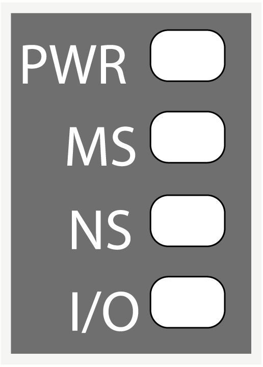
The following graphic shows the LEDs of TM3 bus coupler:

The following table describes the status LEDs:
|
LED |
Color |
Status |
Description |
|---|---|---|---|
|
PWR |
Green |
On |
Power is applied. |
|
Off |
Power is removed. All LED indicators are off. |
||
|
MS |
Green/Red |
Flashing |
Device is performing its self-test. |
|
Green |
Solid |
Device is running. |
|
|
Flashing |
Device detected an invalid configuration or is not configured. |
||
|
Red |
Solid |
Device detected an error, that is, under most circumstances, unrecoverable. |
|
|
Flashing |
Device detected an error, that is, under most circumstances, recoverable. For example: oRotary switch position changed during operational mode. oError detected during firmware update. |
||
|
NS |
Green/Red |
Off |
IP address is not configured. |
|
Flashing |
Device is performing its self-test. |
||
|
Green |
Solid |
At least one CIP connection is established, and an exclusive owner connection has not timed out. |
|
|
Flashing |
The IP address is configured, but CIP connections are not established and an exclusive owner connection has not timed out. |
||
|
Red |
Solid |
Device detected that the IP address is already in use. |
|
|
Flashing |
An IP address is configured, and an exclusive owner connection for which this device is the target has timed out. |
||
|
I/O |
Green |
Solid |
Device communicates with the expansion modules. |
|
Flashing |
The physical configuration matches the software configuration, but no communication between the bus coupler and the expansion modules. |
||
|
Red |
Solid |
The physical configuration mismatches the software configuration. |
|
|
Flashing |
At least one TM2 or TM3 expansion module did not respond to the bus coupler for three consecutive cycles. |
NOTE: During boot, each LED is ON for a few seconds, then OFF except the PWR LED. The LED behavior rules apply when the boot is completed successfully.