Maximum Hardware Configuration
The TM3 bus coupler is a device designed to manage Ethernet/IP and Modbus TCP communication when using TM2/TM3 expansion modules in a distributed architecture.
Distributed Configuration Principle
The following illustration defines a distributed configuration with a controller:

1 Communication expansion module
2 Controller
3 TM3 bus coupler
4 TM3 expansion modules
5 TM3 transmitter and receiver
TM3 Bus Coupler Distributed Configuration Architecture
Optimized distributed configuration and flexibility are provided by the association of:
oController
oTM3 bus coupler
oTM3 expansion modules
oTM2 expansion modules
The following illustration is an example of an association:

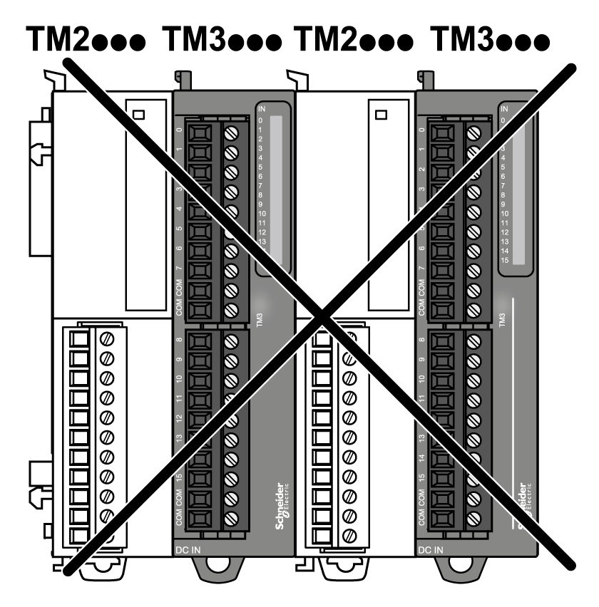
NOTE: It is prohibited to mount a TM2 module before any TM3 module as indicated in the following illustration:

The TM3 bus coupler supports up to:
|
Module type |
Maximum number of modules |
|---|---|
|
TM2 |
7 |
|
TM2 - TM3 |
7 |
|
TM3 |
7 without transmitter and receiver. 14 with transmitter and receiver. |
NOTE: EcoStruxure Machine Expert software validates the configuration in the Configuration window.
NOTE: In some environments, the maximum configuration populated by high consummation modules, coupled with the maximum distance allowable between the TM3 transmitter and receiver modules, may present bus communication issues although the EcoStruxure Machine Expert software allowed for the configuration. In such a case you will need to analyze the consummation of the modules chosen for your configuration, as well as the minimum cable distance required by your application, and possibly seek to optimize your choices.