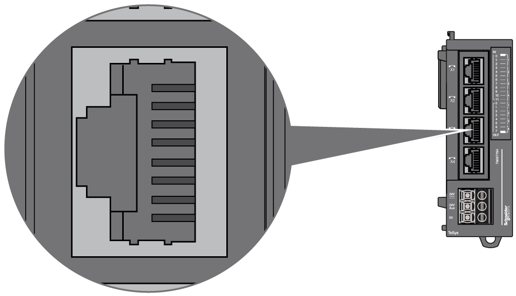
The TM3XTYS4 module is equipped with 4 channels RJ45 connector:

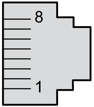
The following graphic and table show the channel RJ45 connector pin assignment:

|
Pin N° |
Designation |
Signal |
Description |
|---|---|---|---|
|
1 |
Output 1 |
Direction 1 control |
Drives the direct (forward) command of the motor. |
|
2 |
Output 2 |
Direction 2 control |
Drives the reverse (backward) command of the motor. |
|
3 |
0 V |
– |
– |
|
4 |
Input 1 |
Ready |
Active if the selector of TeSys is in the ON position. |
|
5 |
Input 2 |
Run |
Input active if the power contacts of TeSys are closed. |
|
6 |
N.C. |
– |
Reserved. Do not connect. |
|
7 |
Input 3 |
Trip |
Input active if the selector of TeSys is in the TRIP position (only for TeSys U). |
|
8 |
24 Vdc input common |
Common for sensors |
Power supply for inputs 1, 2 and 3 (pins 4, 5 and 7). |
|
|
|
UNINTENDED EQUIPMENT OPERATION |
|
Do not connect wires to unused terminals and/or terminals indicated as “No Connection (N.C.)”. |
|
Failure to follow these instructions can result in death, serious injury, or equipment damage. |
|
|
|
INCOMPATIBLE EQUIPMENT |
|
Use the RJ45 connector only for the link with devices which are compatible with the TeSys RJ45 connection system. |
|
Failure to follow these instructions can result in injury or equipment damage. |
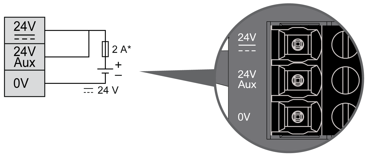
DC Power Supply Wiring Diagram

* type T fuse
24 Vdc Aux is dedicated to inputs power supply.
24 Vdc is dedicated to outputs power supply.
|
|
|
POTENTIAL OF OVERHEATING AND FIRE |
|
oDo not connect the equipment directly to line voltage. oUse only isolating PELV or SELV power supplies to supply power to the equipment1. |
|
Failure to follow these instructions can result in death, serious injury, or equipment damage. |
1 For compliance to UL (Underwriters Laboratories) requirements, the power supply must also conform to the various criteria of NEC Class 2, and be inherently current limited to a maximum power output availability of less than 100 VA (approximately 4 A at nominal voltage), or not inherently limited but with an additional protection device such as a circuit breaker or fuse meeting the requirements of clause 9.4 Limited-energy circuit of UL 61010-1. In all cases, the current limit should never exceed that of the electric characteristics and wiring diagrams for the equipment described in the present documentation. In all cases, the power supply must be grounded, and you must separate Class 2 circuits from other circuits. If the indicated rating of the electrical characteristics or wiring diagrams are greater than the specified current limit, multiple Class 2 power supplies may be used.
For more details, refer to the Wiring Best Practices.