Modulo-loop Mode Principle Description
The Modulo-loop mode can be used for repeated actions on a series of moving objects, such as packaging and labeling applications.
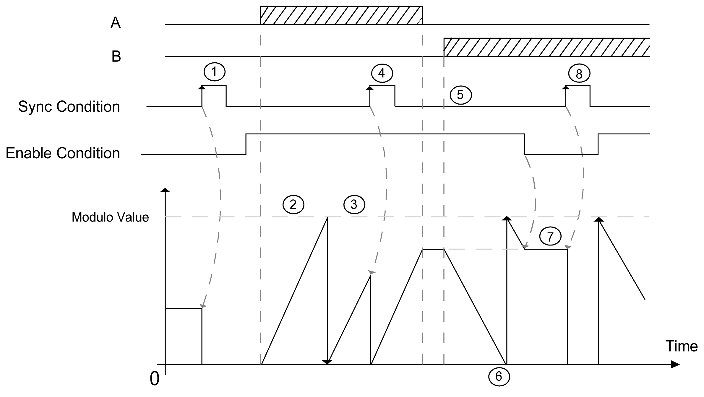
On a rising edge of the Sync condition, the counter is activated and the counter value is set to 0.
When counting is enabled:
Incrementing direction: the counter increments until it reaches the modulo value -1. At the next pulse, the counter is reset to 0, a modulo flag is set to 1, and the counting continues.
Decrementing direction: the counter decrements until it reaches 0. At the next pulse, the counter is set to the modulo value, a modulo flag is set to 1, and the counting continues.
This table shows the 8 types of input modes available:
|
Input Mode |
Comment |
|---|---|
|
A = Up, B = Down |
default mode The counter increments on A and decrements on B. |
|
A = Impulse, B = Direction |
If there is a rising edge on A and B is true, then the counter decrements. If there is a rising edge on A and B is false, then the counter increments. |
|
Normal Quadrature X1 |
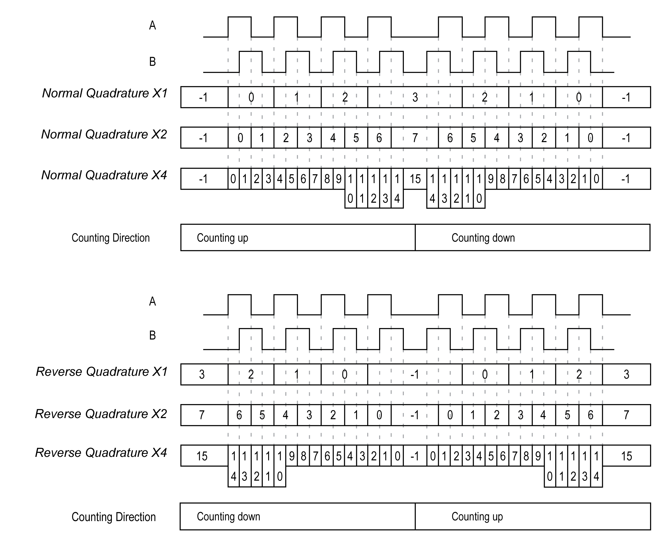
A physical encoder always provides 2 signals 90° shift that first allows the counter to count pulses and detect direction: oX1: 1 count by Encoder cycle oX2: 2 counts by Encoder cycle oX4: 4 counts by Encoder cycle |
|
Normal Quadrature X2 |
|
|
Normal Quadrature X4 |
|
|
Reverse Quadrature X1 |
|
|
Reverse Quadrature X2 |
|
|
Reverse Quadrature X4 |

|
Stage |
Action |
|---|---|
|
1 |
On the rising edge of Sync condition, the counter value is reset to 0 and the counter is activated. |
|
2 |
When Enable condition = 1, each pulses on A increments the counter value. |
|
3 |
When the counter reaches the (modulo-1) value, the counter loops to 0 at the next pulse and the counting continues. Modulo_Flag is set to 1. |
|
4 |
On the rising edge of Sync condition, the counter value is reset to 0. |
|
5 |
When Enable condition = 1, each pulse on B decrements the counter. |
|
6 |
When the counter reaches 0, the counter loops to (modulo-1) at the next pulse and the counting continues. |
|
7 |
When Enable condition = 0, the pulses on the inputs are ignored. |
|
8 |
On the rising edge of Sync condition, the counter value is reset to 0. |
NOTE: Enable and Sync conditions depends on configuration. These are described in the Enable and Preset function.
The encoder signal is counted according to the input mode selected, as shown below:
