Performance and Safety Integrity Levels
This table describes the performance and safety integrity levels associated to the 1 channel application:
|
Application type |
Performance Level (PL) and maximum category (IEC/ISO 13849-1) |
Maximum Safety Integrity Level (SIL) (IEC/EN 62061) |
|---|---|---|
|
1 channel application |
PL c, category 2 |
SIL 1 |
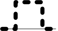
The inputs and outputs behavior description may be based on chronograms. In those chronograms, the following convention on signals status applies:
|
I/O behavior |
Status |
|---|---|

|
On |

|
Off |

|
Optional |
Both the safety conditions and the start conditions must be valid before allowing the activation of outputs.
|
|
|
UNINTENDED EQUIPMENT OPERATION |
|
Do not use either the monitored start or the non-monitored start as a safety function. |
|
Failure to follow these instructions can result in death, serious injury, or equipment damage. |
This table presents the module types available in a 1 channel application with a non-monitored start:
|
Reference |
Channel 1 |
Start + EDM 1 |
EDM 2 |
Outputs |
|---|---|---|---|---|
|
TM3SAC5R |
+24 Vdc - A1 |
Y1-Y2 |
– |
13-14 23-24 33-34 |
|
TM3SAK6R |
S11-S12 |
S33-S39 |
S41-S42 |
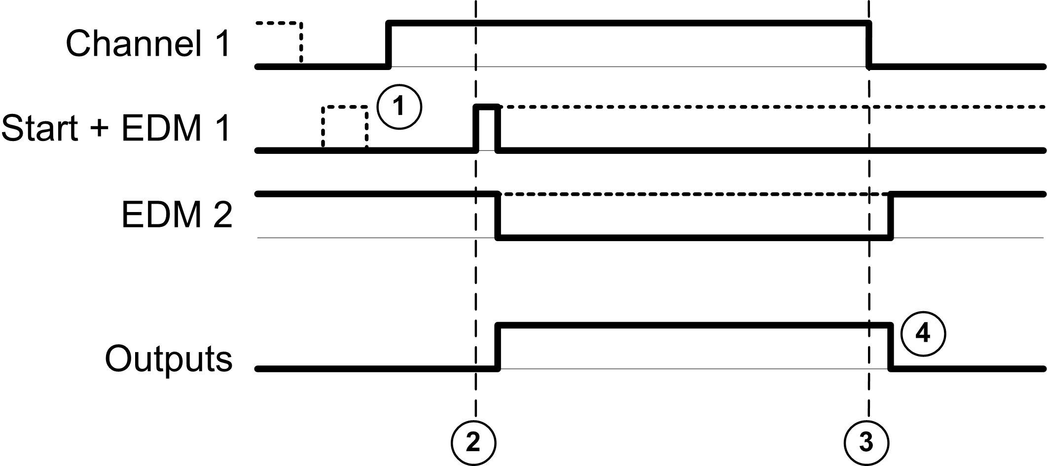
This figure represents the output activation management in a 1 channel application with a non-monitored start:

Events description:
1.Non-monitored start condition is available as long as the start input is on.
The start condition can be valid before the safety input.
The outputs are on only if start + safety input conditions are valid.
2.Safety inputs + start conditions are valid
3.Safety inputs condition invalid
4.The outputs react to the safety input and start conditions with a delay given by system constraints.
This table presents the module type available in a 1 channel application with a monitored start:
|
Reference |
Channel 1 |
Start + EDM 1 |
EDM 2 |
Outputs |
|---|---|---|---|---|
|
TM3SAK6R |
S11-S12 |
S33-S34 |
S41-S42 |
13-14 23-24 33-34 |
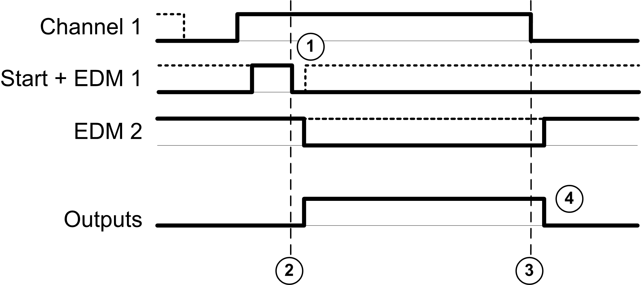
This figure represents the output activation management in a 1 channel application with a monitored start:

Events description:
1.Monitored start condition is triggered by a falling edge on the start input.
2.Safety inputs + start conditions are valid
3.Safety inputs condition invalid
4.The outputs react to the safety input and start conditions with a delay given by system constraints.