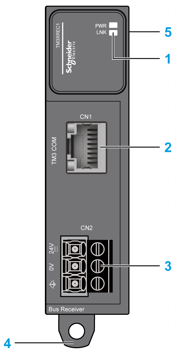
Receiver module:
oOne RJ45 connector for communication
oRemovable 24 Vdc power supply terminal block
The following figures show the parts of the TM3 receiver expansion module:

|
Label |
Elements |
Refer to |
|---|---|---|
|
1 |
LEDs for displaying the link activity and power supply status. |
– |
|
2 |
TM3 bus port |
– |
|
3 |
Power supply screw terminal block. |
|
|
4 |
Clip-on lock for 35 mm (1.38 in.) DIN-rail. |
|
|
5 |
Expansion connector for I/O bus (right side only). |
– |
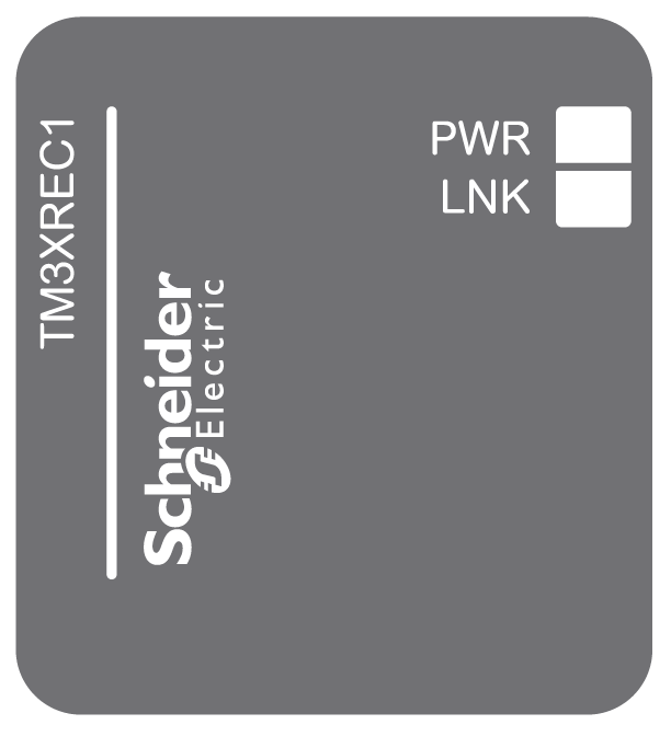
The following figure shows the status LEDs:

This table describes the status LEDs:
|
LED |
Color |
Status |
Description |
|---|---|---|---|
|
Power (PWR) |
Green |
On |
Power supply for TM3 bus is available. |
|
Off |
Power supply for TM3 bus is not available. |
||
|
Link (LNK) |
Green |
On |
Link/data signal is detected from the transmitter. |
|
Off |
No link/data signal is detected from the transmitter. |