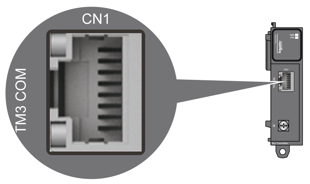
The TM3XTRA1 is equipped with an RJ45 connector.

Rules for Connection to the Functional Ground
The following table shows the characteristics of the screw to be used with the provided Functional Ground (FE) Cable:

Applying torque above the limit may damage the terminal screw or threads.
|
NOTICE |
|
INOPERABLE EQUIPMENT |
|
Do not tighten screw terminals beyond the specified maximum torque (Nm / lb-in.). |
|
Failure to follow these instructions can result in equipment damage. |
NOTE: You must connect the functional ground (FE) of the TM3 transmitter module to the same functional ground connected to your controller. Without the functional ground connection, the TM3 transmitter module may not establish communication with the TM3 receiver module.
|
NOTICE |
|
INOPERABLE EQUIPMENT |
|
oEnsure that the functional ground cable is securely connected between the functional ground screw of the TM3 transmitter module and the functional ground of the controller. oMonitor the status of the TM3 bus within your application to determine the correct behavior of the TM3 bus in case of disconnection from the functional ground of the TM3 transmitter module. |
|
Failure to follow these instructions can result in equipment damage. |