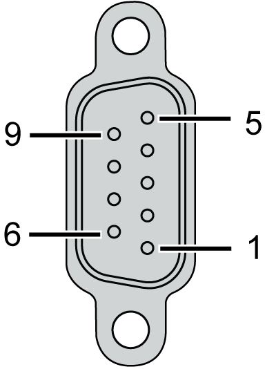
The TM4PDPS1 module is equipped with 1 PROFIBUS DP SUB-D 9 connector:

The figure shows the PROFIBUS DP SUB-D 9 connector pins:

The table describes the PROFIBUS DP SUB-D 9 connector pins assignment:
|
Pin N° |
PROFIBUS DP |
Description |
|---|---|---|
|
1 |
Reserved |
– |
|
2 |
Reserved |
– |
|
3 |
RxD/TxD-P |
Transmit/receive data High |
|
4 |
CNTR-P |
Transmit enable High |
|
5 |
DGND |
Signal Ground |
|
6 |
VP |
Voltage 5 V (100 mA) |
|
7 |
Reserved |
– |
|
8 |
RxD/TxD-N |
Transmit/receive data Low |
|
9 |
Reserved |
– |
Rules for Connection to the Functional Ground
The following table shows the characteristics of the screw to be used with the provided Functional Earth (FE) Cable:

Applying torque above the limit may damage the terminal screw or threads.
|
NOTICE |
|
INOPERABLE EQUIPMENT |
|
Do not tighten screw terminals beyond the specified maximum torque (Nm / lb-in.). |
|
Failure to follow these instructions can result in equipment damage. |