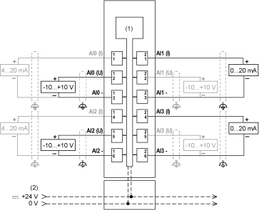
The following figure shows the wiring diagram for TM5SAI4L:

(1): Internal electronics
(2): 24 Vdc I/O power segment integrated into the bus bases
(I): Current
(U): Voltage
Use shielded, properly grounded cables for all analog and high-speed inputs or outputs and communication connections. If you do not use shielded cable for these connections, electromagnetic interference can cause signal degradation. Degraded signals can cause the controller or attached modules and equipment to perform in an unintended manner.
|
|
|
UNINTENDED EQUIPMENT OPERATION |
|
oUse shielded cables for all fast I/O, analog I/O and communication signals. oGround cable shields for all analog I/O, fast I/O and communication signals at a single point1. oRoute communication and I/O cables separately from power cables. |
|
Failure to follow these instructions can result in death, serious injury, or equipment damage. |
1Multipoint grounding is permissible if connections are made to an equipotential ground plane dimensioned to help avoid cable shield damage in the event of power system short-circuit currents.
|
|
|
UNINTENDED EQUIPMENT OPERATION |
|
Do not connect wires to unused terminals and/or terminals indicated as “No Connection (N.C.)”. |
|
Failure to follow these instructions can result in death, serious injury, or equipment damage. |
If you have physically wired the analog channel for a voltage signal and you configure the channel for a current signal in EcoStruxure Machine Expert, you may damage the analog circuit.
|
NOTICE |
|
INOPERABLE EQUIPMENT |
|
Verify that the physical wiring of the analog circuit is compatible with the software configuration for the analog channel. |
|
Failure to follow these instructions can result in equipment damage. |