The table below describes the main characteristics of the TM5SAI2TH module:
|
Main Characteristics |
||
|---|---|---|
|
Number of input channels |
2 |
|
|
Measurement type |
Temperature |
Voltage |
|
Input sensor type |
J, K, N, S, B and R thermocouple sensors |
|
|
Input range |
Type J: -210...1200°C (-346...2192°F) Type K: -270...1372°C (-454...2501°F) Type N: -270...1300°C (-454...2372°F) Type S: -50...1768°C (-58...3214°F) Type B: 0...1820°C (32...3308°F) Type R: -50...1768°C (-58...3214°F) 1 µV per bit 2 µV per bit |
± 65.534 mV |
|
Resolution |
16-bit |
|
The thermocouple modules are configured as a whole for the same type of thermocouple sensor. You cannot mix thermocouple sensor types on the same module, otherwise the temperature readings will not be correct.
|
|
|
UNINTENDED EQUIPMENT OPERATION |
|
oOnly connect thermocouple sensors of the same type to the temperature module. oConfigure the module for the correct type of thermocouple. |
|
Failure to follow these instructions can result in death, serious injury, or equipment damage. |
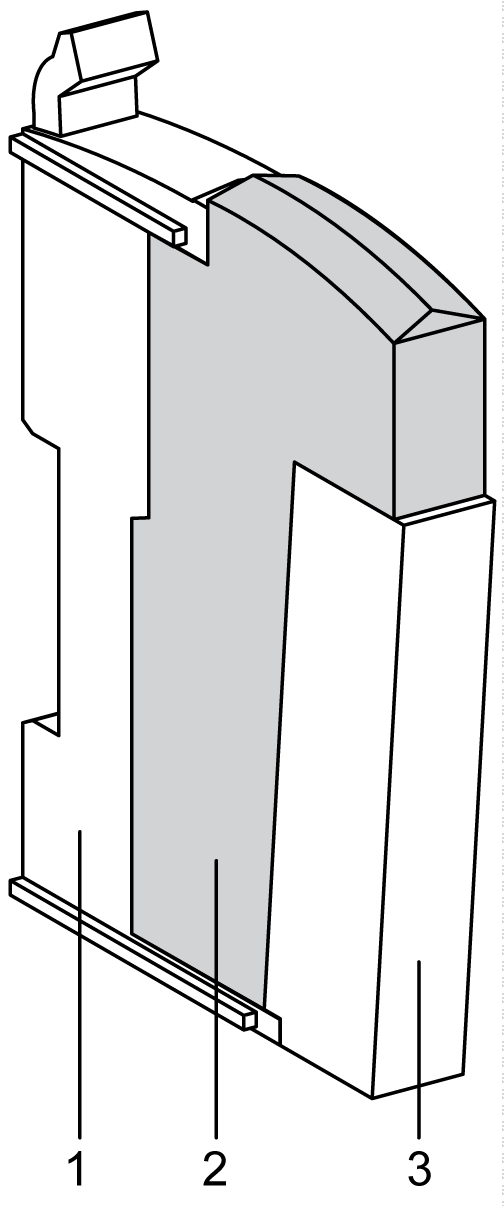
The following figure shows the slice with a TM5SAI2TH:

The table below shows the model numbers for the terminal block and bus base associated to TM5SAI2TH:
|
Number |
Model Number |
Description |
Color |
|---|---|---|---|
|
1 |
TM5ACBM11 or TM5ACBM15 |
Bus base
Bus base with address setting |
White
White |
|
2 |
TM5ASAI2TH |
Electronic module |
White |
|
3 |
TM5ACTB06 or TM5ACTB12 |
Terminal block, 6 pins
Terminal block, 12 pins |
White
White |
NOTE: For more information, refer to TM5 bus bases and terminal blocks
The following figure shows theTM5SAI2TH status LEDs:

The table below shows theTM5SAI2TH status LEDs:
|
LEDs |
Color |
Status |
Description |
|---|---|---|---|
|
r |
Green |
Off |
No power supply |
|
Single Flash |
Reset state |
||
|
Flashing |
Preoperational state |
||
|
On |
Normal operation |
||
|
e |
Red |
Off |
OK or no power supply |
|
On |
Detected error or reset state |
||
|
Single Flash |
Detected error for an I/O channel. |
||
|
e+r |
Steady Red / Single Green Flash |
Invalid firmware |
|
|
0-1 |
Green |
Off |
Channel not configured |
|
Flashing |
Overflow, underflow or broken wire detected |
||
|
On |
The analog/digital converter is running, value is available |
||