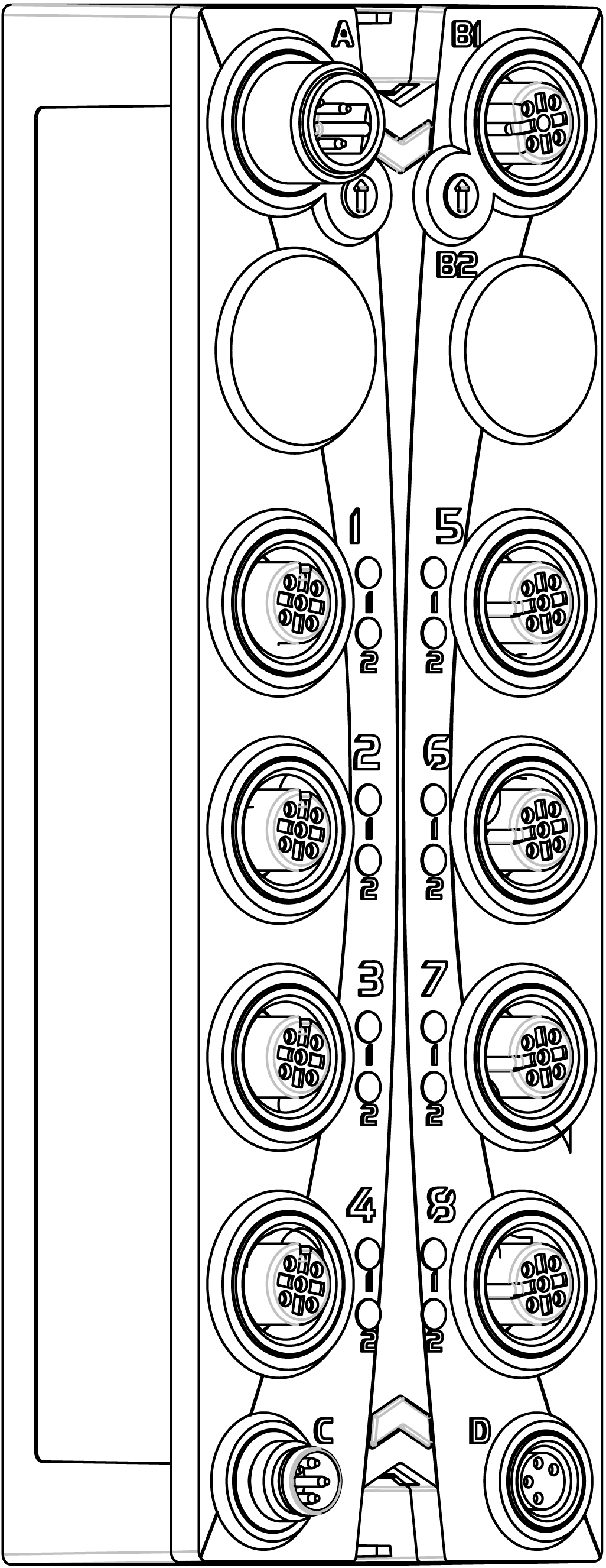
The following table describes the main features of the Safety Digital Mixed module TM7SDM12DTFS:
|
Main Features |
|
|---|---|
|
Number of Inputs |
8 |
|
Input Type |
safety-related digital inputs and configurable input filter |
|
Input Circuit |
sink |
|
Number of Outputs |
o8 test (pulse) outputs o4 safety-related digital FET outputs |
|
Rated Voltage |
24 Vdc |
|
|
|
POTENTIAL FOR EXPLOSION |
|
oOnly use this equipment in non-hazardous locations or in locations that comply either with the Class I, Division 2, Groups A, B, C and D, or with the ATEX Group II, Zone 2 specifications for hazardous locations, depending on your local and/or national regulations. oDo not substitute components which would impair compliance to the hazardous location specifications of this equipment. oDo not connect or disconnect equipment unless power has been removed or the location is known to be non-hazardous. |
|
Failure to follow these instructions will result in death or serious injury. |
This figure presents the TM7SDM12DTFS module:

The following table presents the reference of the module:
|
Model Number |
Description |
Color |
|---|---|---|
|
TM7SDM12DTFS |
TM7 Safety Digital Mixed module |
red |
NOTE: For more information, refer to:
This figure presents the status LED indicators:

1 Status LED indicators r and e: left green r, right red e
2 Status LED indicators S and E: left red S, right red E
The following tables describe the status LED indicators:
|
LED indicator |
Color |
Status |
Description |
|---|---|---|---|
|
r |
off |
Module supply not connected. |
|
|
green |
single flash |
reset mode |
|
|
double flash |
firmware update in progress |
||
|
flashing |
pre-operational state |
||
|
on |
RUN state |
||
|
e |
off |
No error detected or module supply not connected. |
|
|
red |
flashing |
boot loader mode |
|
|
triple flash |
firmware update in progress |
||
|
on |
error detected |
||
|
r+e |
steady red/single green flash |
invalid configuration |
|
|
LED indicator |
Color |
Status |
Description |
|---|---|---|---|
|
1- 1 1- 2 2- 1 2- 2 5- 1 5- 2 6- 1 6- 2 |
red |
on |
Indicates either an error has been detected for the corresponding input or that the safety-related input is being used as a non-safety-related input. NOTE: When there is no connection to the Safety Logic Controller, all channels are steady red. |
|
flashing |
detected error in 2-channel evaluation (synchronous flashing of two affected channels). |
||
|
green |
on |
input set |
|
LED indicator |
Color |
Status |
Description |
|---|---|---|---|
|
4- 1 4- 2 8- 1 8- 2 |
red |
on |
Indicates either an error has been detected for the corresponding output or that the safety-related output is being used as a non-safety-related output. NOTE: When there is no connection to the Safety Logic Controller, all channels are steady red. |
|
orange |
on |
output set |
|
LED indicator |
Color |
Status |
Description |
|---|---|---|---|
|
S E |
off |
RUN state or 24 Vdc supply not present |
|
|
red |

|
boot phase or missing TM5 link or non-functioning processor (refer to safety message below) |
|

|
pre-operational state |
||

|
communication channel is not OK |
||

|
firmware for this module is a non-certified pilot version NOTE: If you observe this indication, you must immediately replace the module, or update its firmware with a certified version. In all cases, contact your Schneider Electric representative. |
||

|
boot phase, inoperable firmware |
||
|
on |
Safety-related status is active. |
||
Whenever the S and E LED indicators are illuminated continuously, this indicates that the module is inoperative. There is also a diagnostic available in the Safety Logic Controller to indicate this state. Replacement of the module must be made immediately. It is your responsibility to ensure all necessary repairs are made promptly to enable proper functionality.
|
|
|
LOSS OF SAFETY FUNCTION |
|
oImmediately replace any and all modules that indicate that they are in an inoperable state. oEnsure that the effect on un-repaired equipment is taken into account in your risk assessment. oMake all necessary repairs to equipment before re-starting, or continuing service of, your machine. |
|
Failure to follow these instructions can result in death, serious injury, or equipment damage. |