The table below provides the main characteristics of the TM7BDM16B block:
|
Main characteristics |
||
|---|---|---|
|
Number of input/output channels |
16 |
|
|
Input type |
Type 1 |
|
|
Input signal type |
Sink |
|
|
Output type |
Transistor, 0.5 A max. |
|
|
Output signal type |
Source |
|
|
Sensor and actuator connection type |
M8, female connector type |
|
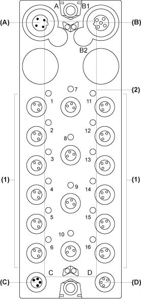
The following figure shows the TM7BDM16B block:

(A) TM7 bus IN connector
(B) TM7 bus OUT connector
(C) 24 Vdc power IN connector
(D) 24 Vdc power OUT connector
(1) Input / Output connectors
(2) Status LEDs
Connector and Channel Assignments
The table below provides the connector and channel assignments of the TM7BDM16B block. For further information, refer to I/O Configuration Tab:
|
I/O connectors |
I/O status LEDs |
Channel types |
Channels |
|---|---|---|---|
|
1 |
1 |
Input / Output |
I0 / Q0 |
|
2 |
2 |
Input / Output |
I1 / Q1 |
|
3 |
3 |
Input / Output |
I2 / Q2 |
|
4 |
4 |
Input / Output |
I3 / Q3 |
|
5 |
5 |
Input / Output |
I4 / Q4 |
|
6 |
6 |
Input / Output |
I5 / Q5 |
|
7 |
7 |
Input / Output |
I6 / Q6 |
|
8 |
8 |
Input / Output |
I7 / Q7 |
|
9 |
9 |
Input / Output |
I8 / Q8 |
|
10 |
10 |
Input / Output |
I9 / Q9 |
|
11 |
11 |
Input / Output |
I10 / Q10 |
|
12 |
12 |
Input / Output |
I11 / Q11 |
|
13 |
13 |
Input / Output |
I12 / Q12 |
|
14 |
14 |
Input / Output |
I13 / Q13 |
|
15 |
15 |
Input / Output |
I14 / Q14 |
|
16 |
16 |
Input / Output |
I15 / Q15 |
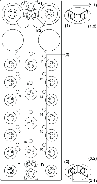
The following figure shows the status LEDs of the TM7BDM16B block:

(1) TM7 bus status LEDs, set of two LEDs: 1.1 (green) and 1.2 (red)
(2) I/O status LEDs, composed of sixteen LEDs (orange)
(3) I/O block status LEDs, set of two LEDs: 3.1 (green) and 3.2 (red)
The table below provides the TM7 bus status LEDs of the TM7BDM16B block:
|
TM7 bus status LEDs |
Description |
|
|---|---|---|
|
LED 1.1 |
LED 1.2 |
|
|
OFF |
OFF |
No power supply on TM7 bus |
|
ON |
ON |
TM7 bus in preoperational state: opower supply on TM7 bus and oblock not initialized |
|
ON |
OFF |
TM7 bus in operational state |
|
OFF |
ON |
TM7 bus error detected |
The table below provides the I/O status LEDs of the TM7BDM16B block:
|
Channel LEDs |
State |
Description |
|---|---|---|
|
1 to 16 |
OFF |
Corresponding input/output deactivated |
|
1 to 16 |
ON |
Corresponding input/output activated |
The table below provides the I/O block status LEDs of the TM7BDM16B block:
|
Block status LEDs |
State |
Description |
|---|---|---|
|
3.1 |
OFF |
No power supply |
|
Single Flash |
Reset state |
|
|
Flashing |
Preoperational state |
|
|
ON |
Operational state |
|
|
3.2 |
OFF |
OK or no power supply |
|
Single Flash |
Detected error for an I/O channel: oDI: Overflow or underflow of the input signal oDO: Overcurrent or short circuit |
|
|
Double Flash |
Power supply not in the valid range |
|
|
ON |
Detected error or reset state |