This cartridge has a removable spring terminal block for the connection of the inputs.
The following figure shows an example of 3-wire RTD and thermocouple probe connections:

(1): RTD
(2): Thermocouple
A: External power supply
The following figure shows an example of a pair of 3-wire RTD connections:

(1): RTD
A: External power supply
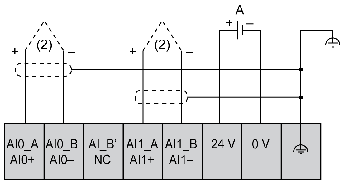
The following figure shows an example of a pair of thermocouple connections:

(2): Thermocouple
A: External power supply
The following figure shows an example of 4-wire RTD and thermocouple connections:

(1): RTD
(2): Thermocouple
A: External power supply
NOTE: Each input can be connected to either an RTD or thermocouple probe.
|
|
|
UNINTENDED EQUIPMENT OPERATION |
|
Do not connect wires to unused terminals and/or terminals indicated as “No Connection (N.C.)”. |
|
Failure to follow these instructions can result in death, serious injury, or equipment damage. |