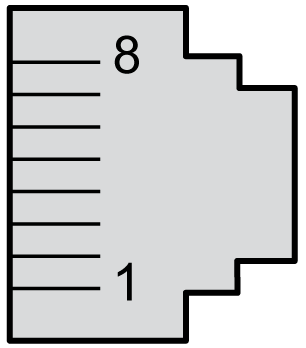
The TMSES4 module is equipped with four Ethernet RJ45 connectors:

The following illustration shows the Ethernet RJ45 connector pin assignment:

The following table describes the Ethernet connector pin assignment:
|
Pin N° |
100BASE-T |
1000BASE-T |
|---|---|---|
|
1 |
TD+ |
DA+ |
|
2 |
TD- |
DA- |
|
3 |
RD+ |
DB+ |
|
4 |
N.C. |
DC+ |
|
5 |
N.C. |
DC- |
|
6 |
RD- |
DB- |
|
7 |
N.C. |
DD+ |
|
8 |
N.C. |
DD- |
NOTE: The controller supports the MDIO auto-crossover cable function. It is not necessary to use special Ethernet crossover cables to connect devices directly to this port (connections without an Ethernet hub or switch).
NOTE: Ethernet cable disconnection is detected every second. In case of disconnection of a short duration (< 1 second), the network status may not indicate the disconnection.