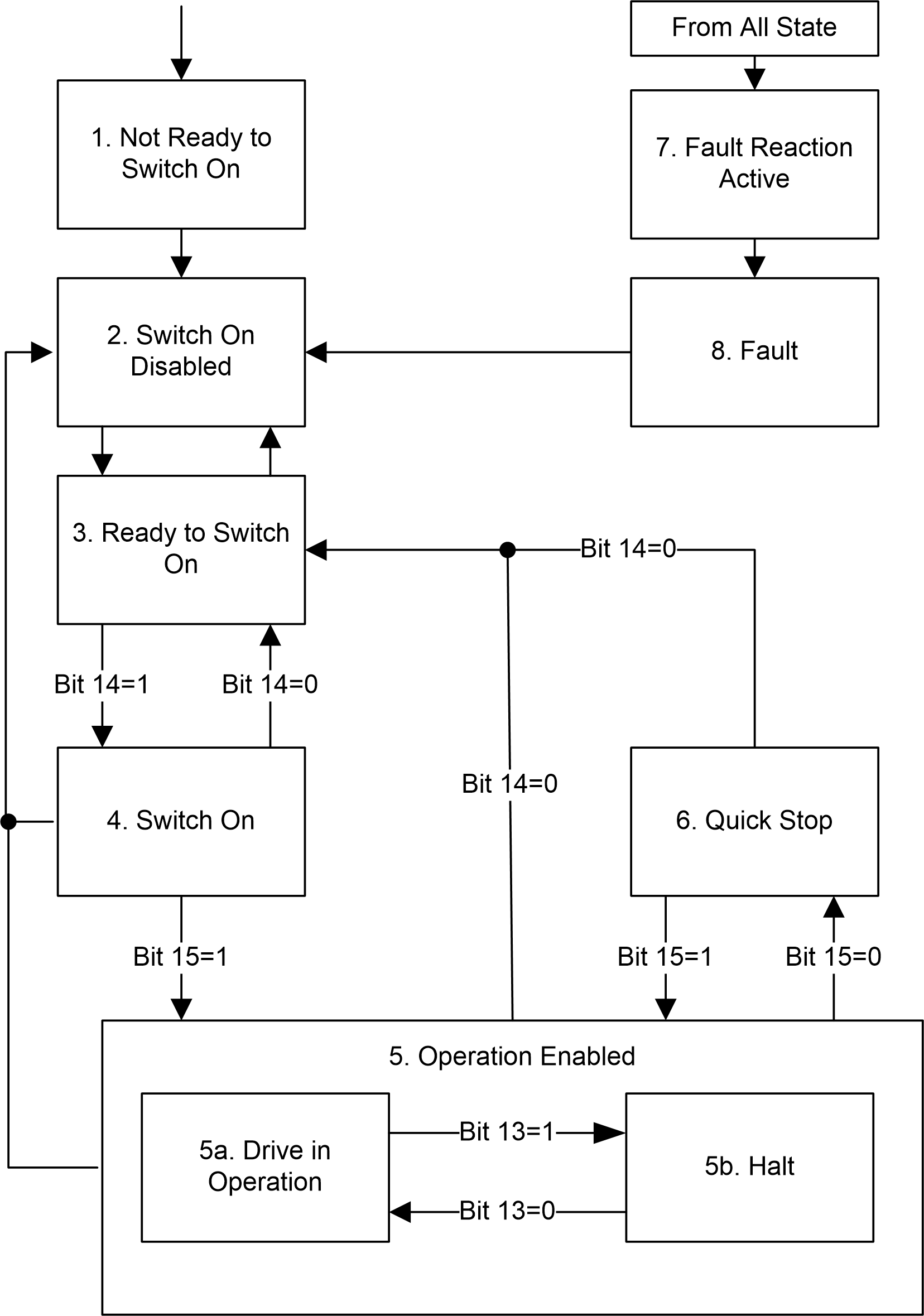
Sercos III Operating State Diagram
After switching on and when an operating mode is started, the product goes through a number of operating states.
The state diagram (state machine) shows the relationships between the operating states and the state transitions. The operating states are internally monitored and influenced by monitoring functions.
The following figure shows the Sercos III state diagram:

Description of Operating States
|
Operating State |
Description |
|---|---|
|
1 - Not ready to switch on |
Initialization starts. This is a transient state invisible to the communication network. |
|
2 - Switch on disabled |
The power stage is not ready to switch on. The drive is locked, no power is supplied to the motor. The configuration and adjustment parameters can be modified. |
|
3 - Ready to switch on |
The power stage is ready to switch on and awaiting power stage supply mains. The drive is locked, no power is supplied to the motor. The configuration and adjustment parameters can be modified. |
|
4 - Switched on |
Power stage is switched on. The drive is locked, no power is supplied to the motor. The power stage of the drive is ready to operate, but voltage has not yet been applied to the output. The adjustment parameters can be modified. If a configuration parameter is modified, the drive returns to the state 2 - Switch on disable . |
|
5 - Operation enabled |
Power stage is enabled. The drive is in running state In this operating state, two states can be dissociated: o5a - Drive in operation: The drive is running. o5b - Halt active: The drive is halted. |
|
6 - Quick stop active |
A quick stop of the drive is being executed. |
|
7 - Fault reaction active |
Transient state during which the drive performs an action corresponding to the selected error response. |
|
8 - Fault |
Error response terminated. Power stage is disabled. The drive is locked, no power is supplied to the motor. |