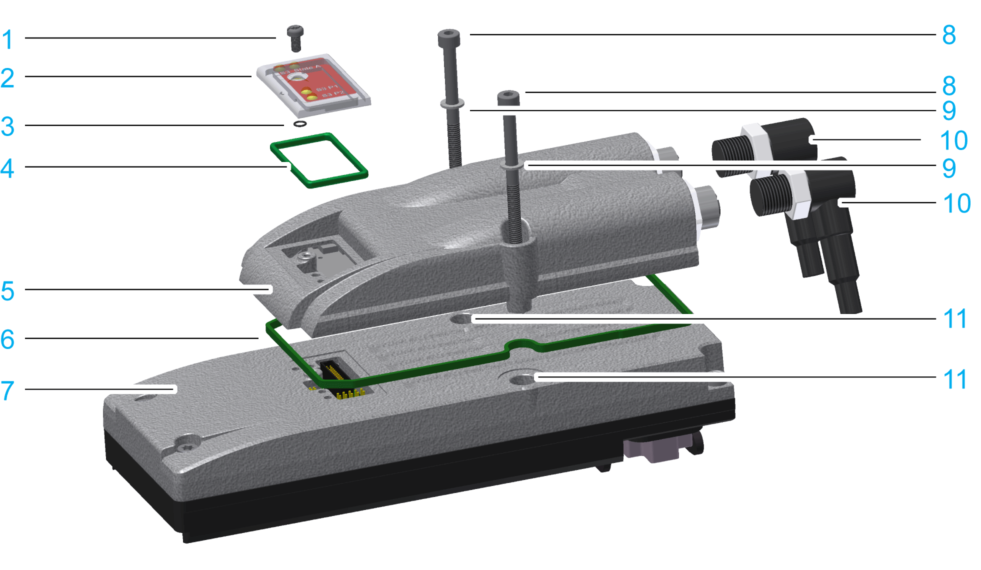
Lexium 62 ILM Digital I/O Module - Installation

1 Torx M3x6 screw
2 Protective cover
3 Insulating washer, 2.5 x 0.6 mm (0.1 x 0.02 in.)
4 Protective cover gasket
5 Lexium 62 ILM digital I/O module
6 Sealing ring for the Lexium 62 ILM digital I/O module
7 Lexium 62 ILM Integrated Servo Drive
8 Hexagon socket screw M4x50
9 Serrated lock washers M4
10 M12 connectors (X4, X5)
11 Mounting holes of the Lexium 62 ILM
Before beginning the replacement of specific components, read thoroughly the section Replacing Components and Cables for important safety information and general instructions.
The following tools are required for installation:
oHexagon socket screwdriver 3.0
oTorx TX10 screwdriver
Check delivery for completeness:
oLexium 62 ILM digital I/O module with sealing ring
oTwo Torx screws M4x50
oTwo x serrated lock washers M4
Observe the following instructions to help prevent damages due to electrostatic discharge.
|
NOTICE |
|
ELECTROSTATIC DISCHARGE |
|
oDo not touch any of the electrical connections or components. oPrevent electrostatic charges, for example, by wearing appropriate clothing. oIf you must touch circuit boards, do so only on the edges. oRemove existing static charge by touching a grounded, metallic surface. |
|
Failure to follow these instructions can result in equipment damage. |
|
Step |
Action |
|---|---|
|
1 |
Set main switch to OFF position, or otherwise remove all power to the system. |
|
2 |
Prevent main switch from being switched back on. |
|
3 |
Loosen the screw (1) with the screwdriver (Torx). |
|
4 |
Remove screw (1) with insulating washer (3) and protective cap (2) and protective cap gasket (4) from Lexium 62 ILM. |
|
5 |
Loosen the screws in the mounting holes (11) (M4x28) with the screwdriver (hexagon socket). |
|
6 |
Remove the screws and serrated lock washers. |
|
7 |
Insert the sealing ring (6) into the groove of the Lexium 62 ILM digital I/O module. |
|
NOTICE |
|
INSUFFICIENT SHIELDING/GROUNDING/SEALING |
|
The serrated lock washers must be removed from their original position (11) when removing screws. |
|
Failure to follow these instructions can result in equipment damage. |
|
Step |
Action |
|---|---|
|
1 |
Attach the Lexium 62 ILM digital I/O module on Lexium 62 ILM. |
|
2 |
Plug screws (8) (M4x50) with serrated lock washers (9) through the Lexium 62 ILM digital I/O module into Lexium 62 ILM. |
|
3 |
Gently turn the screw (8) inward with a screwdriver (hexagon socket). |
|
4 |
Tighten the screws (8) temporary with 2 Nm (17.70 lbf in). |
|
5 |
Tighten the screws (8) with 3 Nm (26.55 lbf in) definitively. |
|
6 |
Fit protective cap (2) together with protective cover seal (4) onto the Lexium 62 ILM digital I/O module. |
|
7 |
Screw the protective cap on tightly (to 1 Nm) with the screw (1) and the insulating washer (3) by using a Torx screwdriver. |
|
NOTICE |
|
LOSS OF IP67 RATING |
|
oAlign the Lexium 62 ILM Digital I/O Module with the three fixing pins. oBe sure that the sealing ring of the Lexium 62 ILM Digital I/O Module is completely inserted into the groove of the Lexium 62 ILM. |
|
Failure to follow these instructions can result in equipment damage. |